instruction manual
Axcess Central Controllers
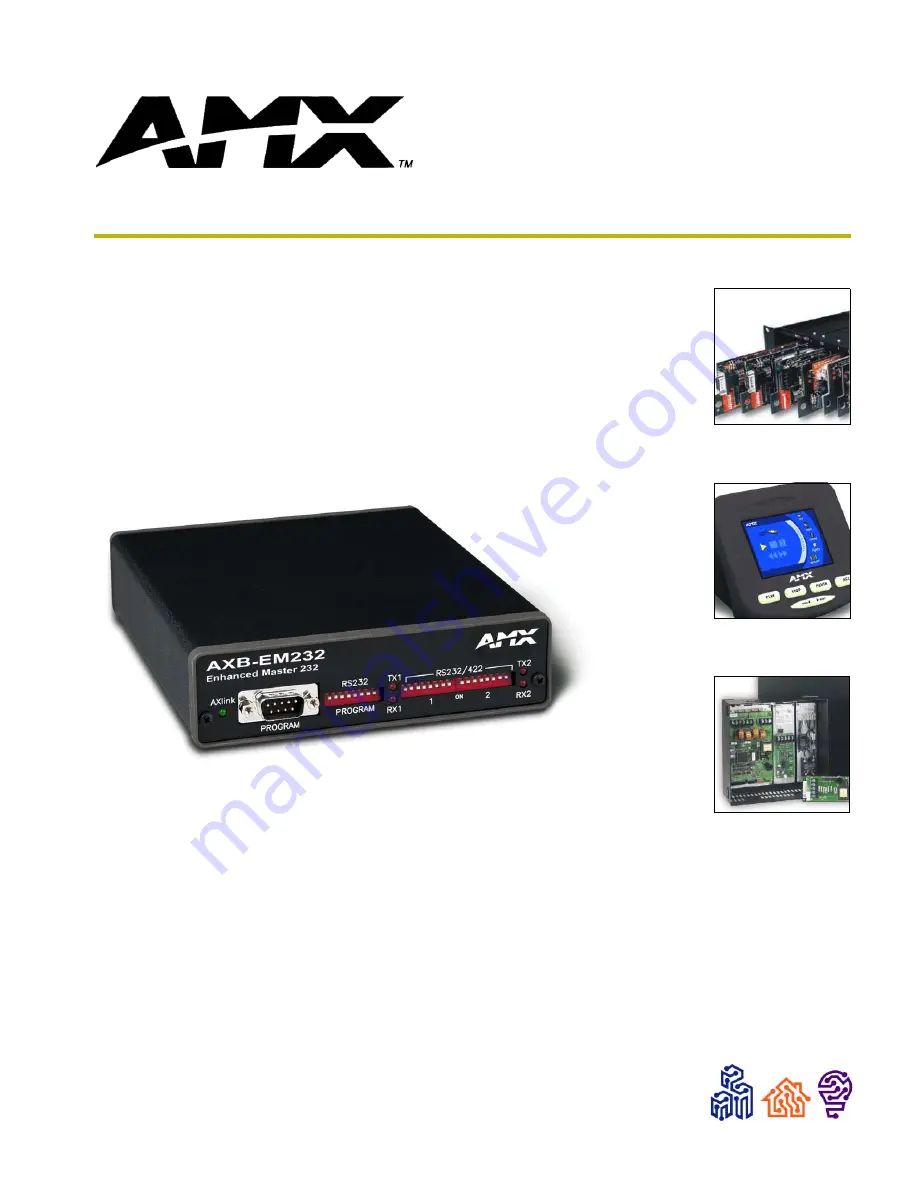
AXB-EM232
Enhanced Master RS-232 Controller
Страница 1: ...instruction manual Axcess Central Controllers AXB EM232 Enhanced Master RS 232 Controller ...
Страница 2: ... liability applies whether damages are sought or a claim is made under this warranty or as a tort claim including negligence and strict product liability a contract claim or any other claim This limitation of liability cannot be waived or amended by any person This limitation of liability will be effective even if AMX Corporation or an authorized representative of AMX Corporation has been advised ...
Страница 3: ... Devices to the AXB EM232 4 Preparing captive wires 4 Using AXlink 4 Using Ports 1 and 2 for RS 232 data communication 5 Using Port 1 for RS 422 communication 6 Using Port 1 for RS 485 data communication 6 Using the 12 VDC power supply 6 RS 232 male program connector 7 Replacing the Lithium Batteries 7 Mounting the AXB 232 In an Equipment Rack 8 Programming 9 Send_Commands 9 Send_Strings 10 Xmodem...
Страница 4: ...ii AXB EM232 Enhanced Master RS 232 Controller Table of Contents ...
Страница 5: ...s complete Axcess programs and controls other AXlink components and two devices using RS 232 as a control protocol It can also control devices using RS 422 and RS 485 protocols FIG 1 AXB EM232 Front and rear panel components RS 232 RS 232 422 AXlink PWR 12VDC RX PROGRAM RS 232 CTS2 RTS2 V AXlink RX2 TX2 GND TX TX PROGRAM TX1 RS 232 422 485EN RX TX1 GND RX1 RX1 1 PWR AXM GND AXP ON 2 TX2 RX2 AXlink...
Страница 6: ... TX1 and RX1 LEDs The red LEDs indicate that the AXB EM232 is receiving RX or transmit ting TX RS 232 RS 422 or RS 485 data RX1 and TX1 correspond to Port 1 on the rear panel See Rear Panel Components for a description of Port 1 RS 232 422 1 and 2 DIP Switches The two 8 position DIP switches configure the communication parame ters for the Ports 1 and 2 See Rear Panel Components for a description o...
Страница 7: ... the front panel refasten the two screws and plug in the two wire power connector Setting DIP switches Configure the device and programming communication ports baud rate data bits stop bits and parity Use the eight position DIP switches on the front panel to set the communications parameters RS 232 PROGRAM DIP switch Use the eight position RS 232 Program DIP switch to set the communications parame...
Страница 8: ...ction Do not tighten the screws excessively doing so may strip the threads and damage the connector Using AXlink Connect the AXlink wiring to the connector on the AXB EM232 as shown in FIG 3 Communication Parameters DIP Switch Settings Switch 1 2 3 4 5 6 7 8 Function Stop Bits Data Bits Parity Baud Rates Setting Off Off Off Off Off Off Off Off Value 2 bits 7 bits Unused 300 On On On Off Off On Off...
Страница 9: ...gure the AXB EM232 for hardware handshaking request to send clear to send by connecting the RS 232 wiring to Port 2 as shown in FIG 6 FIG 4 RS 232 Port 1 wiring FIG 5 RS 232 Port 2 wiring FIG 6 RS 232 Port 2 wiring for hardware handshaking GND RX1 TX1 485EN RX1 RX1 TX1 TX1 GND TX RX Device not used RS232 422 Port 1 GND RX2 TX2 CTS2 RTS2 GND TX RX Device not used RS232 Port 2 GND RX2 TX2 CTS2 RTS2 ...
Страница 10: ...icating via RS 485 connect the RS 485 wiring to Port 1 as shown in FIG 8 RS 485 communication is available only through Port 1 You must ground the 485EN pin Using the 12 VDC power supply Connect the optional 12 VDC power supply to the two wire power connector to apply power as shown in FIG 9 FIG 7 RS 422 Port 1 wiring FIG 8 RS 485 Port 1 wiring FIG 9 12 VDC Power connector wiring GND RX1 TX1 485EN...
Страница 11: ...dvertent loss of data and prevent an unnecessary service outage 1 Discharge the static electricity from your body 2 Unplug the 2 pin power connector and any other connectors 3 Remove the two screws on the front panel 4 Remove the front panel and slide the circuit board out of the enclosure Program Connector and Pinouts Pin Signal 2 RXD 3 TXD 4 12 VDC 5 GND 7 12 VDC Pin 1 Pin 9 Only an AMX Programm...
Страница 12: ... 10 Replace the front panel and refasten the two screws 11 Reconnect any connectors you removed Mounting the AXB 232 In an Equipment Rack To rack mount the AXB EM232 using an optional AC RK Accessory Rack Kit 1 Remove any all connectors from the rear panel 2 Remove the two screws on the front panel and remove the front panel and the space bracket behind the panel 3 Use a blade or other sharp objec...
Страница 13: ...ting to be sent to Master will be cleared TXCLR Any characters waiting in the transmit out buffer will be cleared and transmis sion will stop B9MON Enables a special 9 data bits with 1 stop bit mode which overrides the DIP switch settings for number of data stop and parity bits The baud rate is locked on at the current DIP switch setting on issuance of this command B9MOFF Sets data bits mode to no...
Страница 14: ...0 microsecond increments 1 255 Sends a break character of the specified length of time 27 18 1 Sets the 9 data bit to 1 for all subsequent characters to be transmitted Used with the B9MON com mand 27 18 0 Clears the 9 data bit to 0 for all subsequent charac ters to be transmitted Used with the B9MON com mand 27 19 time in 1 millisecond increments 1 255 Inserts a delay before the next character to ...
Страница 15: ...Programming 11 AXB EM232 Enhanced Master RS 232 Controller ...
Страница 16: ...ve richardson TX 75082 USA 469 624 8000 800 222 0193 fax 469 624 7153 technical support 800 932 6993 032 004 1013 10 03 2003 AMX Corporation All rights reserved AMX the AMX logo the building icon the home icon and the light bulb icon are all trademarks of AMX Corporation AMX reserves the right to alter specifications without notice at any time In Canada doing business as Panja Inc ...