


Specifications Information and Repair Parts Manual 4381-96 and 4382-96
4381-252-00
1
09/2012
Please read and save this Repair Parts Manual. Read this manual and the General Operating Instructions carefully before attempting to assemble,
install, operate or maintain the product described. Protect yourself and others by observing all safety information. The Safety Instructions are contained
in the General Operating Instructions. Failure to comply with the safety instructions accompanying this product could result in personal injury and/or
property damage! Retain instructions for future reference
.
AMT reserves the right to discontinue any model or change specifications at any time without
incurring any obligation.
©2012 American Machine & Tool Co., Inc. of PA, A Subsidiary of The Gorman-Rupp Company, All Rights Reserved.
Periodic maintenance and inspection is required on all pumps to insure proper operation. Unit must be clear of debris and sediment. Inspect for leaks and loose bolts. Failure
to do so voids warranty.
1-Inch Dewatering Pump
Refer to pump manual 1808-633-00 for General Operating and Safety Instructions.
DESCRIPTION
These centrifugal pumps are engine driven, self-priming (to 15 ft. lift), portable units, shipped completely assembled and mounted. A clog-resistant, open
impeller is used to handle clear or dirty liquids, but is not intended for the handling of large solids. A built-in check valve assists in priming and a
mechanical seal prevents leakage. All seals are Buna N. Applications include sprinkling, spraying, irrigation, draining, or general dewatering. Handle
liquids from 40º to 180º F (4º to 82º C). For use with nonflammable, non-abrasive liquids compatible with pump component materials.
MAINTENANCE
Pump model 4381-96 incorporates a 2-cycle engine as its driver.
2-cycle oil must be mixed with gasoline (24 parts gasoline to 1
part 2-cycle oil) to ensure performance and prevent severe engine
damage. Refer to mixing instructions provided in the engine
booklet and plates on the engine.
To prevent accidental starting always remove spark plug or
disconnect and ground spark plug wire before attempting to
service or remove any component
.
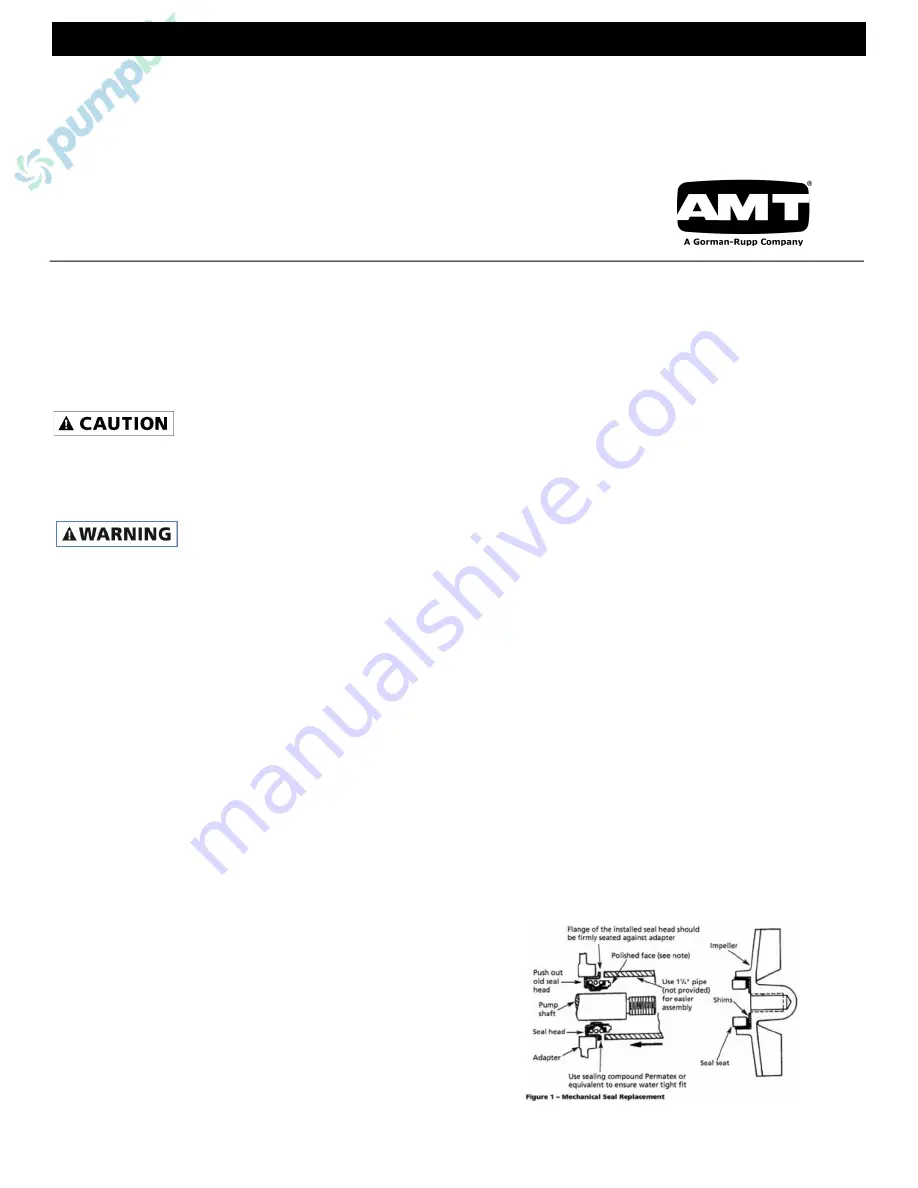
MECHANICAL SEAL REPLACEMENT
Refer to Figures 1 and 2
IMPORTANT
: Always replace both seal seat and seal head (Ref. No.
4) to ensure proper mating of components!
1.
Unscrew fasteners and remove pump casing (Ref. No. 8)
and O-ring from adapter (Ref. No. 3).
2.
Unthread fasteners and remove volute (Ref. No. 6) and
flapper valve (Ref. No. 7) from adapter.
3.
A) 4381 ONLY:
Unscrew impeller from engine shaft.
Remove impeller shim (Ref. No. 5) from engine shaft.
B) 4380 ONLY:
Remove impeller fastener (Ref. No. 5) by
unscrewing in counterclockwise direction. Slide impeller and
shims (Ref. No. 5) from keyed shaft.
NOTE:
To keep shaft from turning, remove shroud from engine and
hold flywheel in place. 4381-96 impeller is screwed on to the right
(CW). To unscrew, turn impeller to the left (CCW) when facing
impeller.
4.
Unthread fasteners and remove adapter from engine
mounting face.
5.
Lay adapter face down on a flat, stable surface and press
seal cartridge from adapter.
6.
Pry seal seat from rear of impeller with a screwdriver or
other suitable means. Clean recess in adapter for seal
cartridge and recess in impeller for seal seat before inserting
any new parts.
7.
Inspect polished face (do not touch faces) of seal seat and
polished face of seal head to ensure they are clean and not
marred.
8.
Press new seal head into recess in adapter. A sealing
compound (such as silicon or Permatex) may be used to
assure a water-tight fit on outside of seal head.
9.
Wet rubber portion of seal seat with a light coating of soapy
water.
10.
Replace any impeller shims removed in disassembly (See
Figure 1).
11.
Press seal seat squarely into cavity in impeller. If seal seat
does not press squarely into cavity, it can be adjusted in
place by pushing on it with a piece of pipe, wooden dowel or
the like. Always use a piece of cardboard between pipe and
seal seat to avoid scratching polished face of seal seat. This
is a lapped surface and must be handled very carefully.
12.
Secure adapter on engine mounting face.
13.
Install impeller back in place (CW), tightening until it is
against shaft.
14.
Remount volute, positioning O-ring in place.
IMPORTANT:
Always inspect O-ring. Replace when cracked or worn.
Wet O-ring and flapper valve with oil or Vaseline for ease of assembly.
15.
Remount casing.
SHIM ADJUSTMENT
1.
When installing a replacement engine, adapter, impeller,
shaft sleeve, volute or casing, it may be necessary to vary
the number of impeller shims (Ref. No. 5) that will be
required. This is easily done by adding one shim more than
was removed and reassembling the pump as described in
MECHANICAL SEAL REPLACEMENT section.
NOTE:
When adding or removing shims, it is best to proceed with a
0.010" increment each time. Remove spark plug wire from engine and
ground. While tightening unit together turn shaft (by pulling on recoil
starter), etc.); feel for shaft seizing. If shaft begins to seize before
fasteners are completely tight, disassemble pump and remove one
shim and repeat assembly.
2.
Once having added one shim more than original, ensure that
volute (Ref. No. 6) and adapter (Ref. No. 3) are firmly fitted
(check fasteners). When engine turns freely, add shims until
it does strike, then remove a 0.010" shim. This should allow
proper clearance.
3.
Proper running clearance for impeller should be as close as
possible to volute without striking; maximum clearance is
1/32" (0.032").
4.
Follow above procedure until proper clearance is obtained.
This will ensure maximum performance.
Содержание 4381-96
Страница 3: ......
Страница 4: ...www amtpump com ...


