


[Type text]
3993-252-00 1
2/2015
Specifications Information and Repair Parts Manual
3993-99
Please read and save this Repair Parts Manual. Read this manual and the General Operating Instructions carefully before attempting to assemble,
install, operate or maintain the product described. Protect yourself and others by observing all safety information. The Safety Instructions are contained
in the General Operating Instructions. Failure to comply with the safety instructions accompanying this product could result in personal injury and/or
property damage! Retain instructions for future reference
.
AMT reserves the right to discontinue any model or change specifications at any time without
incurring any obligation.
©2015 AMT Pump Company, A Subsidiary of The Gorman-Rupp Company, All Rights Reserved.
Periodic maintenance and inspection is required on all pumps to insure proper operation. Unit must be clear of debris and sediment. Inspect for leaks and loose bolts. Failure
to do so voids warranty.
4-Inch Trash Pedestal Pump
Refer to pump manual 1808-635-00 for General Operating and Safety Instructions.
DESCRIPTION
This self-priming (to 20 ft. lift) centrifugal pump includes a clog resistant, open impeller capable of handling solids as large as 2" diameter (up to 25% by
volume). A built-in check valve assists in priming and a mechanical seal prevents leakage. All seals are Buna N. Handles liquids from 40º to 180º F (4º
to 82º C). For use with nonflammable liquids compatible with pump component materials.
Performance Chart
Power Req.
GPM at Total Head in Feet
Max**
HP
RPM
10'
20'
30'
40'
50'
60'
70'
80'
90'
100'
110'
Head
15
3600
630 600 560 520 475 425 370 310 240 170 85 120
ft.
(**) Shut-off; to convert to psi, divide by 2.31.
MAINTENANCE
To prevent accidental starting always remove the spark plug, or
disconnect and ground the spark plug wire before attempting to service
or remove any component.
CLEANING
These units are designed so that for most cleanout or clogging
problems it should not be necessary to remove hoses or piping. The
suction area and impeller chambers can be reached by removing (2)
threaded handles (Ref. No. 33) and removing suction cleanout cover
plate (Ref. No. 31) and gasket (Ref. No. 30).
NOTE:
When replacing cleanout cover plate, carefully wipe clean all
surfaces on which gasket has contact. Also, make sure gasket is in
position.
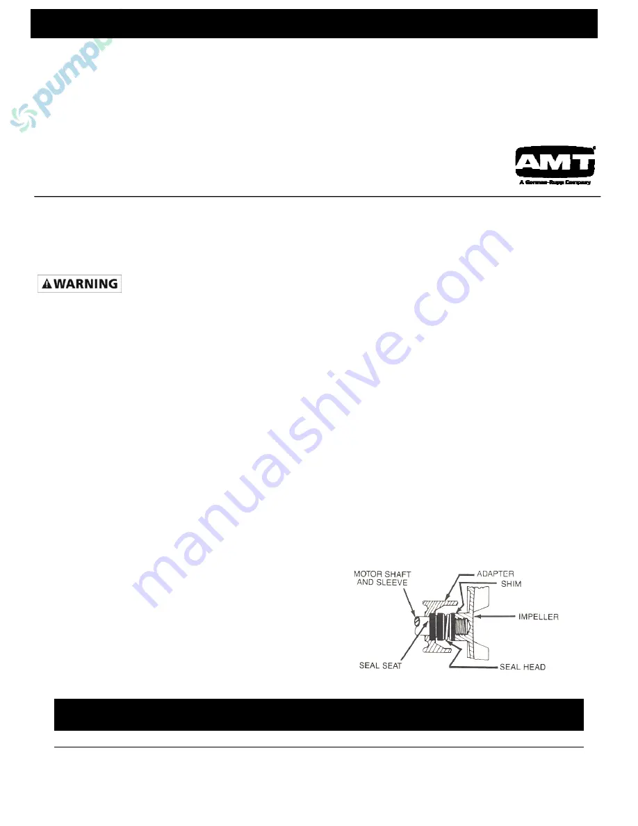
MECHANICAL SEAL REPLACEMENT
Refer to Figures 1 and 2
NOTE:
Always replace seal seat (Ref. No. 14), seal head (Ref. No.
15), and shaft sleeve (Ref. No. 16) to ensure proper mating of
mechanical seal components!
1.
Unthread fasteners (Ref. No. 28) and remove casing (Ref.
No. 39) and casing seal (Ref. No. 13) from adapter (Ref. No.
12).
2.
Unthread screws (Ref. No. 19) and remove volute (Ref. No.
20) from adapter.
3.
Unscrew impeller (Ref. No. 18) from pump shaft (Ref. No. 5).
Remove impeller shims (Ref. No. 17), shaft sleeve and seal
head from pump shaft. Use a rubber mallet or soft block of
wood to loosen impeller. Turn it counterclockwise.
4.
Unthread fasteners (Ref. Nos. 7 & 8) and remove adapter
from pedestal mounting face.
5.
Push seal seat from adapter recess with a screwdriver.
6.
Clean adapter recess before inserting a new seal seat.
7.
Carefully wipe polished surface of new seal seat with a clean
cloth.
8.
Wet the rubber portion of seal seat with a light coating of
soapy water.
9.
Press new seal seat squarely into cavity in adapter. If seal
seat does not press squarely into cavity, it can be adjusted in
place by pushing on it with a piece of pipe. Always use a
piece of cardboard between pipe and seal seat to avoid
scratching seal seat. (This is a lapped surface and must be
handled very carefully.)
10.
After seal seat is in place, ensure that it is clean and has not
been marred.
11.
Using a clean cloth, wipe shaft and make certain that it is
perfectly clean.
12.
Secure adapter on pedestal mounting face.
NOTE:
Tighten fasteners EVENLY to avoid cracking rabbet on
pedestal mounting face.
13.
Apply a light coating of soapy water to the inside rubber
portion of seal head and slide onto shaft sleeve. Slip shaft
sleeve with seal head onto pump shaft.
IMPORTANT:
Before installing new shaft sleeve, apply a bead of non-
hardening, pliable sealant (such as Permatex® Form-A-Gasket® No.
2) to motor shaft shoulder.
14.
Replace any impeller shim removed in disassembly.
15.
Screw impeller back in place tightening until it is seated
against shims and shaft sleeve.
16.
Remount volute with fasteners.
17.
Refer to section entitled “Shim Adjustment” at this time if
shaft sleeve or any other parts listed therein have been
replaced.
18.
Inspect position of flapper valve assembly (Ref. No. 23) to
insure proper movement and seating.
19.
Replace casing seal on volute rabbet.
NOTE:
Always inspect casing seal. Replace when cracked or worn.
Wet casing seal with soapy water for ease of assembly.
20. Remount
casing.
21.
Remount any other parts and reconnect spark plug wire.
Pump should now run with renewed original performance.
Figure 1 – Mechanical Seal


