


Document #120522 Rev-A
18
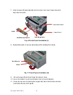
5. Turn over the printer. Remove two screws located near the top cover hinge.
6. Remove the screw from the memory card cover, and left the cover off. Plug in
the cutter driver IC at U14 (M5) / U30 (M5 PLUS) socket on the main board.
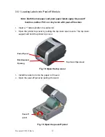
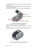
7. Use both thumbs to hold the lower cover and index fingers to lift up the top
cover open levers to separate the lower inner cover and the lower cover.
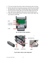
8. Thread the cable through the bezel. Connect the cutter module cable to the
4-pin socket on printer PCB.
Fig. 24 Cutter module installation
Fig. 25 Cutter module cable arrangement
PCB
4-pin Socket
Cutter Cable
Cutter
Lower Inner Cover
Lower Cover
Cutter Cable
Bezel