

8
Temposonics
®
GB-Series SSI
Operation Manual
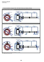
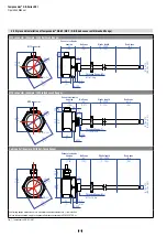
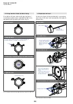
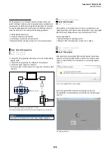
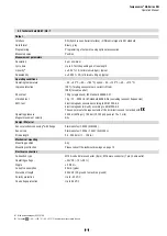
Fig. 3:
Temposonics
®
GB-N / GB-S / GB-K / GB-J
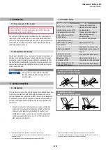
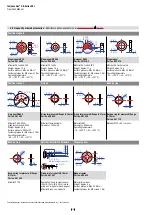
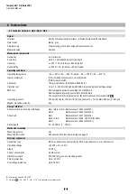
4.2 Styles and installation of Temposonics
®
GB-J / GB-K / GB-N / GB-S
(rod sensor with pressure fit flange)
GB-N / GB-S, example: With M12 connector
Magnet
Ø 10 ± 0.13
(Ø 0.39
± 0.01)
Ø 79 (
Ø 3.11)
13
(0.51)
25
(1)
Ø 18 f7
6
(0.24)
51
(2.01)
M6 (3×)
Ø 64 (
Ø 2.52)
Ø 6.5
(Ø 0.26)
60°
30°
Ø 53 (
Ø 2.09)
Stroke length
25…3250
(1…128)
Null zone
40
(1.57)
Dead zone
63.5
(2.5)
8.1
(0.32)
4.1
(0.16)
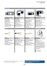
M12 connector
Sensor electronics
housing
34
(1.34)
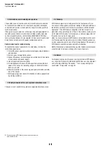
GB-K, example: With M16 connector
Magnet
Ø 79 (
Ø
3.11)
Ø 18 f7
11.3 (0.44)
51
(2.01)
6
(0.24)
25
(1)
Ø 10
(Ø 0.39)
3
(0.12)
22
(0.87)
15
(0.59)
Ø 12.8 ±0.1 (Ø 0.5 ±0.004)
M6 (3×)
Ø 64 (
Ø 2.52)
Ø 6.5
(Ø 0.26)
60°
30°
Ø 53 (
Ø 2.09)
Sensor electronics
housing
34
(1.34)
Stroke length
25…3250
(1…128)
Null zone
40
(1.57)
Dead zone
78.5
(3.1)
8.1
(0.32)
4.1
(0.16)
M16 connector
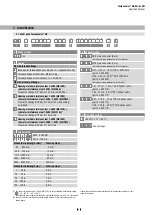
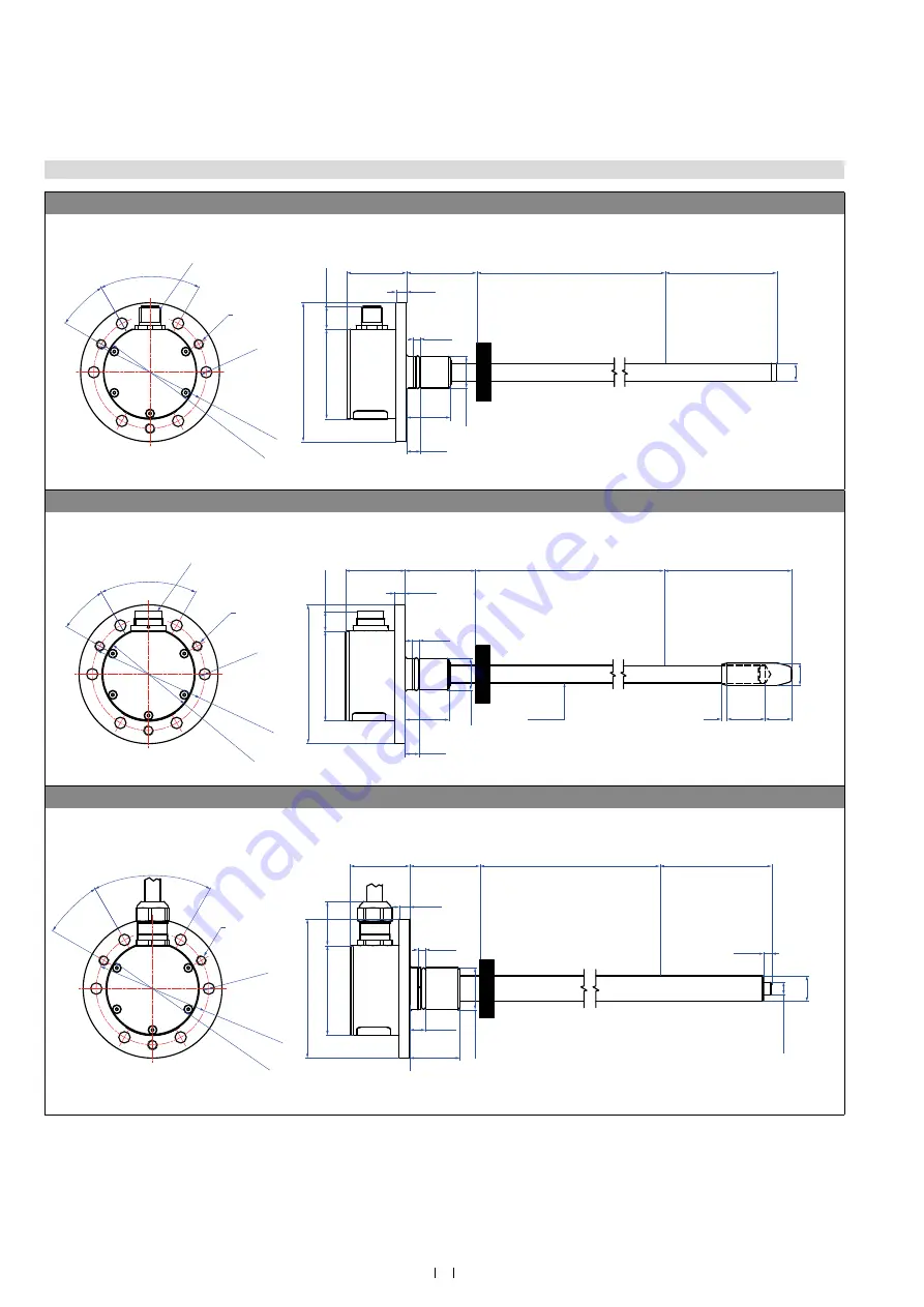
GB-J, example: With cable outlet
Magnet
25 (1)
Ø 79 (3.11)
51
(2.01)
6
(0.24)
M6 (3×)
Ø 6.5
(Ø 0.26)
Ø 64 (
Ø 2.52)
60°
30°
Ø 53 (
Ø 2.09)
Stroke length
25…3250
(1…128)
Null zone
40
(1.57)
Dead zone
73.5
(2.9)
Ø 12.7 ±0.13 (Ø 0.5 ±0.01)
Ø 6.2
(Ø
0.244)
4
(0.16)
4.1
(0.16)
8.05
(0.31)
25
(0.98)
Sensor electronics
housing
34
(1.34)
Ø 21 f6
Controlling design dimensions are in millimeters and measurements in ( ) are in inches