background image


13 


C2LINX 

Amphenol Network Solutions 

All rights reserved. 04.13.20 150717 A0 

509.926.6000 

— amphenol-ns.com 


® 


3.5 Tools and Equipment 

Phillips and flat-head screwdrivers are required. No other tools are needed to assemble the C2LINX chassis and 
corresponding modules. If links need replacement on the chassis, needle-nosed pliers are required to separate 
the links. 

4. C2LINX Chassis Installation  

Please read these instructions carefully before installation. If you need assistance, call Amphenol Network 
Solutions at 509-926-6000 or email us at [email protected].  

Inspect equipment after unpacking and compare it to the packing list.  

Immediately report any shipping damage, defects or missing parts to Amphenol Network Solutions. Keep all 
documentation that comes with your shipment.  

Amphenol Network Solutions is not liable for shipping damage. If the product is damaged, notify the carrier and 
call Amphenol Network Solutions at 509-926-6000 for further recourse.  

NOTE: 

For service or warranty information, please visit amphenol-ns.com and click on the Support tab, email us 

at [email protected] or phone us at 509-926-6000.  

This section covers how to prepare and mount the C2LINX chassis and corresponding modules.  


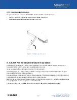
4.1 Install Mounting Brackets on the C2LINX Chassis 

C2LINX chassis includes two mounting brackets and two extension brackets, non-interchangeable, one per side, 
to attach the C2LINX chassis to a 19-inch or 23-inch EIA, ETSI or WECO rack. 


Fig. 4-1: Left side mounting bracket 


Note: Image shows mounting bracket marked for left side 


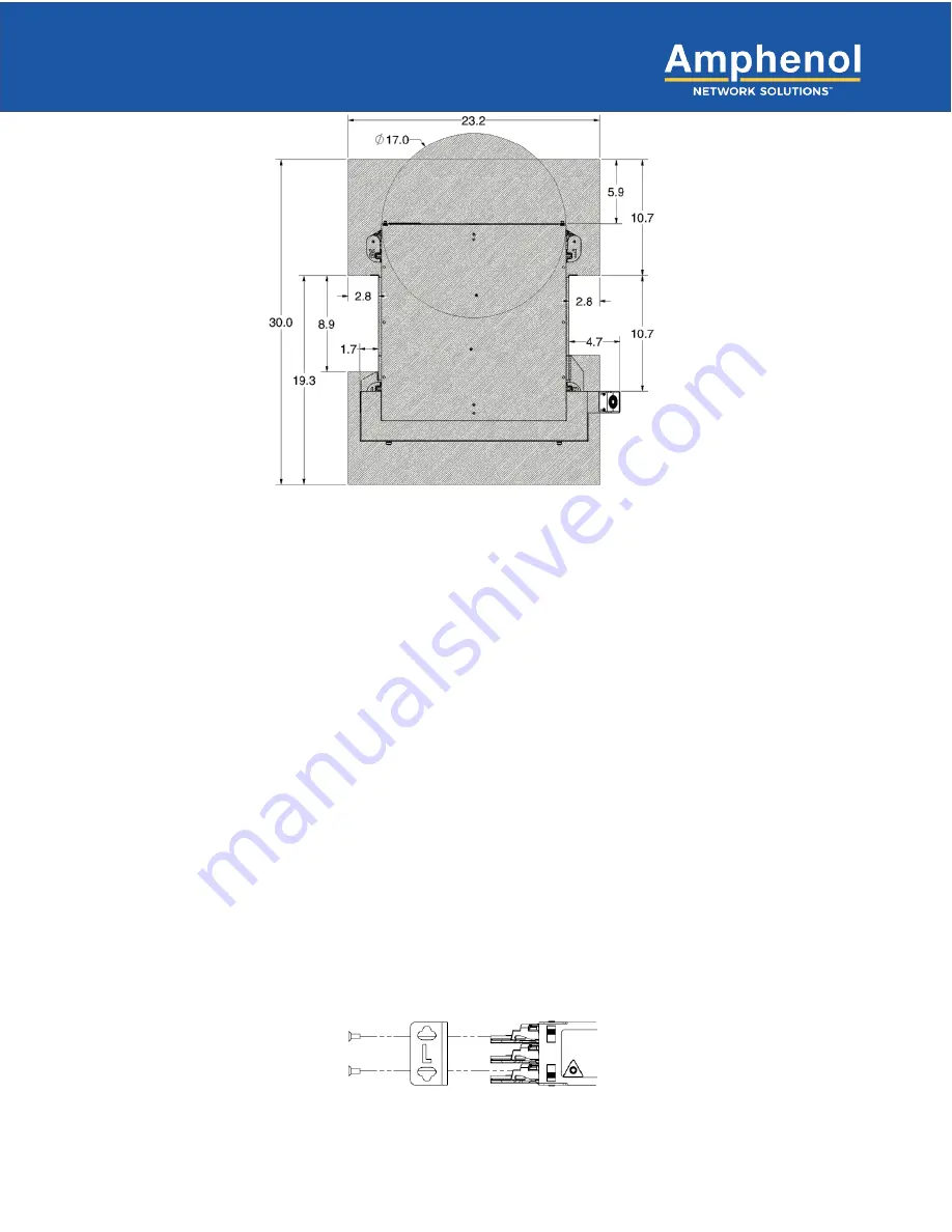
Fig. 3-1: C2LINX working footprint 


Содержание C2LINX Series

Страница 1: ...C2LINX Installation Guide ...

Страница 2: ...of others This document and the products described herein are subject to change without notice About Amphenol Network Solutions is a global innovative original equipment manufacturer that serves the data and communications markets We design manufacture and distribute products for customers who need an end to end solution for network connectivity fiber power distribution and rack management We coll...

Страница 3: ...2 3 4 1 Rack vs Cabinet 12 3 5 Tools and Equipment 13 4 C2LINX Chassis Installation 13 4 1 Install Mounting Brackets on the C2LINX Chassis 13 4 2 Installing the Chassis on the Rack 14 4 3 C2LINX Opening Doors 14 4 3 1 C2LINX Front Door 14 4 3 2 C2LINX Rear Door 15 4 4 Chassis Wall Links 15 4 5 Designation Labels 16 4 5 1 Install Designation Labels 17 5 C2LINX Pre Terminated Module Installation 17 ...

Страница 4: ...s 31 6 9 Splitter Modules 33 6 10 Splice Modules 33 6 10 1 Connecting Fiber Jumpers 37 7 Seismic Latch Installation 38 8 Service 41 8 1 Owner Maintenance 41 8 1 1 High Insertion Loss and the Importance of Cleaning Connectors and Adapters 41 9 Customer Service and Ordering Information 42 9 1 In Warranty Service 42 9 2 Out of Warranty Service 42 9 3 Repackage for Shipment 42 9 4 Ordering Replacement...

Страница 5: ...in rack 20 Fig 5 6 Tab fully engaged showing 20 Fig 5 8 Setting front bracket screws 21 Fig 5 9 Locking tabs 21 Fig 5 10 Installing chassis wall links 22 Fig 5 11 Installing tray links to trays 22 Fig 5 12 Removing thumb screws 23 Fig 5 13 Removing back door and cover thumbscrew s 23 Fig 6 1 Yellow handle 24 Fig 6 2 Opening a tray 24 Fig 6 3 Closing a tray by pushing on the yellow handle 25 Fig 6 ...

Страница 6: ...l ns com Fig 6 21 Tuck fiber under fingers 36 Fig 6 22 Re install clear cover 36 Fig 7 1 Left arm link 38 Fig 7 2 Alignment of hinge 38 Fig 7 3 Right arm link 39 Fig 7 4 Alignment of hinge 39 Fig 7 5 Chassis wall link locations 40 Fig 7 6 Locking the door 40 Fig 9 1 Removing replacing the door 43 ...

Страница 7: ...ns Technical Support at support amphenol ns com or call 509 926 6000 Throughout this guide select information is highlighted in the form of Notes Alerts Cautions and Warnings These notifications are prominent and their importance is indicated as follows NOTE General information to which the user should pay special attention ALERT Important information and or instructions to which the user should a...

Страница 8: ...cking handles This allows easy access to the modules Each tray holds two modules Acronym Abbreviation Term CWDM Coarse Wavelength Division Multiplexing DWDM Dense Wavelength Division Multiplexing IF Intra Facility Fiber IFC Intra Facility Cable LC Local Connector MPO Multi fiber Push On optical fiber module interface type NE Network Element NEBS Network Equipment Building System telecommunications...

Страница 9: ...g of the fibers that can lead to fractures and attenuation 2 2 3 Chassis Wall Links Chassis wall links attach the links to the chassis 2 2 4 Chassis Doors Chassis doors open toward the center of the chassis for space optimization They are easy to remove and re install if necessary See Section 5 for pre terminated rear door installation Left Right Fig 2 2 HD Links Fig 2 3 Chassis wall links Fig 2 4...

Страница 10: ...n brackets are available for mounting the chassis to a 23 inch rack or cabinet See Section 5 for installing pre terminated mounting hardware When installing the chassis in a data center rack install the brackets as far forward as possible This will allow for less cable management issues when fiber is installed in the chassis 2 3 Panel Module Overview C2LINX modules are interchangeable within the C...

Страница 11: ... installed and maintained only by qualified technicians ALERT Install this system according to company requirements It is recommended you install the system in a Restricted Access Location RAL where access is limited through use of tool lock and key or other means of security and be controlled by the authority responsible for the location ALERT Prior to panel installation ensure there is enough sp...

Страница 12: ...g the equipment in an environment compatible with the maximum ambient temperature Tma specified by the manufacturer Mechanical Loading Avoid uneven mechanical loading in the rack This can cause hazardous conditions 3 4 Location and Space The C2LINX chassis requires space in the front and rear for access to patching splicing and cabling Leave as much side clearance for tray and worker access as req...

Страница 13: ...sing parts to Amphenol Network Solutions Keep all documentation that comes with your shipment Amphenol Network Solutions is not liable for shipping damage If the product is damaged notify the carrier and call Amphenol Network Solutions at 509 926 6000 for further recourse NOTE For service or warranty information please visit amphenol ns com and click on the Support tab email us at support amphenol...

Страница 14: ...nstalling the Chassis on the Rack 1 Using a Phillips head screwdriver and the provided 12 24 screws install the chassis on the front of the rack by aligning the mounting holes in the bracket with the holes in the rack Two screws per side are used to attach the chassis to the rack 4 3 C2LINX Opening Doors 4 3 1 C2LINX Front Door Plastic latches are located on the end of each door 1 Pinch latches to...

Страница 15: ...ght They are installed on the appropriate side of the chassis by inserting the bottom clips into the square notches in the plastic rails and then pushing down the top clip to lock in place They can be removed by pushing down on the top clip and then pulling the link up and out 1 Remove chassis wall links from packaging 2 Starting with the bottom most tray Attach the two bottom clips of the chassis...

Страница 16: ...els Designation labels are located on each C2LINX door Designation labels are used to identify adapter fiber jumper information at the front of the panel and connector pigtail fiber information at the rear of the panel Fig 4 7 Installing the tray links to trays Fig 4 8 Designation label Fig 4 6 Installing chassis wall links ...

Страница 17: ...0 or email us at support amphenol ns com Inspect equipment after unpacking and compare it to the packing list Immediately report any shipping damage defects or missing parts to Amphenol Network Solutions Keep all documentation that comes with your shipment Amphenol Network Solutions is not liable for shipping damage If the product is damaged notify the carrier and call Amphenol Network Solutions a...

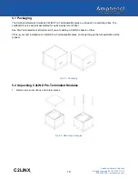
Страница 18: ...ox The cardboard box is easily disassembled for quick deployment of fiber See Pre Terminated Quick Start Guide if you are adding a C2LINX chassis or fiber If this is your first installation of C2LINX Pre Terminated Modules continue through the full installation of the product 5 2 Unpacking C2LINX Pre Terminated Modules 1 Remove top cover of box and corner pieces Fig 5 1 Packaging Fig 5 2 Removing ...

Страница 19: ...s Install 7 inch rack mount slide brackets to the desired RU space on the rack 1 Remove rack mount slide brackets from packaging 2 Align mounting holes on the bracket with the holes on the front of the rack 3 Using a Phillips head screwdriver install the slide brackets onto the rails with the 12 24 screws provided NOTE Do not tighten securely to the rack This allows easier alignment for chassis to...

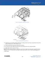
Страница 20: ...d out of protective packaging 3 Align rail guides that are attached to the chassis to the pre installed mounting brackets from the rear of rack NOTE Rail guides are pre installed to chassis You will not need to install them after unpacking 4 Push the chassis all the way forward You will hear a click on both sides of the chassis Ensure tabs have fully engaged Fig 5 5 Sliding chassis into mounting b...

Страница 21: ...g Rack Bracket If you need to remove the chassis 1 Depress the locking tab slightly with your finger 2 Once locking tab has been pushed pull chassis out to unlock 3 Repeat on opposite side to fully release chassis from the rack and mounting brackets 4 Both sides can be done at same time Depress locking tab Fig 5 8 Setting front bracket screws Fig 5 9 Locking tabs Front ...

Страница 22: ... pushing down the top clip to lock in place They can be removed by pushing down on the top clip and then pulling the link up and out 1 Remove chassis wall links from packaging 2 Open doors and remove white foam block from chassis 3 Starting with the bottom most tray Attach the two bottom clips of the chassis wall links into the square notches on the chassis side wall Fig 5 11 4 Rotate chassis wall...

Страница 23: ...0717 A0 509 926 6000 amphenol ns com 5 7 Removing Back Cover and Door 1 Unscrew the thumbscrew s located on the back cover 2 Remove center thumbscrew or nylatch on back cover on rear door Fig 5 12 Removing thumb screws Fig 5 13 Removing back door and cover thumbscrew s ...

Страница 24: ...rd you 3 Using your thumb and index finger grab the yellow handle of the tray you wish to open Fig 6 1 4 Pulling it up and out to open the tray Fig 6 2 6 2 Closing a Tray 1 Using the yellow handle push the tray back into the chassis and fold the links into place in front of the tray Fig 6 3 2 Turn the yellow handle into the chassis to secure the tray in place The handle locks into position Fig 6 4...

Страница 25: ...ng a Module 1 Insert the module into the desired space on the tray Slightly angle the module and slide it back on the surface of the tray until you hear the module click into place on the tray Fig 6 5 Installing a module Fig 6 3 Closing a tray by pushing on the yellow handle Fig 6 4 Tray closing and in locked position ...

Страница 26: ... adapter port for the fiber jumper being installed NOTE To protect fibers work with one fiber jumper at a time Only remove the dust cap for the fiber jumper being installed 4 Clean adapter port with oil free canned compressed air to remove any dust that has accumulated 5 Remove the protective cover from the fiber jumper by pulling it straight out 6 Inspect the end of the fiber jumper for any dust ...

Страница 27: ...tray until it clicks into place 14 Route the cable jumpers through the faceplate Fig 6 9 15 Release the cable link tabs by gently pushing down and rotating them away from the locking tab Fig 6 10 16 Lace cables through the links Fig 6 10 17 Once the cables are routed return tabs to their lock position by pushing and rotating them so they lock under the locking tab Fig 6 10 Fig 6 7 Labeling the fib...

Страница 28: ... the handle to lock into place 20 Go to the front of the chassis and pull the tray out by pulling up and out on the yellow handle 21 Repeat steps 3 9 from section 6 5 above NOTE Amphenol Network Solutions requires the use of G 657 A1 fiber and recommends using G 657 A2 bend insensitive 1 6 or 1 2 mm fiber with short boots to further protect the fiber also LC with low profile triggers are recommend...

Страница 29: ...odule The shuttle was designed to move patch connectors from the back to the front of the chassis when the cassette has been partially populated without removing the whole cassette 1 Locate the front of the tray where you want to add fiber Using the yellow handle pull the tray out Fig 6 12 If replacing fiber detach the fiber to be replaced 2 Push the tray to close 3 Go to the rear of the tray and ...

Страница 30: ... dust cap for the fiber jumper being installed 14 Clean adapter port with oil free canned compressed air to remove any dust that has accumulated 15 Remove the protective cover from the fiber jumper by pulling it straight out 16 Inspect the end of the fiber jumper for any dust or debris If needed clean the fiber with lint wipes and a commercial solution formulated for cleaning fiber surfaces or a r...

Страница 31: ...y in place 6 7 Installing MPO Modules Follow the same procedure as 6 5 Configuring and Installing Patch Modules to install MPO modules making sure to clean and inspect all fibers before making the connections 6 8 Installing Pre Terminated Modules 1 In the rear of the chassis open the desired tray 2 Place the module adapter side first into the tray 3 Push module forward until it clicks into place o...

Страница 32: ...pe to dry the fiber 15 Inspect again to ensure fiber end is clean 16 Repeat Steps 11 15 if needed NOTE After confirming the fiber jumper end is clean do not wipe the fiber or allow it to touch anything before installing it in the adapter 17 Insert the clean dry fiber into the adapter port 18 Route the fiber on the front of the chassis through the links as shown below NOTE Amphenol Network Solution...

Страница 33: ...r or allow it to touch anything before installing it in the adapter 13 Insert the clean dry fiber into the adapter port 14 Route the fiber through the links NOTE Amphenol Network Solutions requires the use of G 657 A1 fiber and recommends using G 657 A2 bend insensitive 1 6 or 1 2 mm fiber with short boots to further protect the fiber also LC with low profile triggers are recommended 15 Repeat ste...

Страница 34: ... to be spliced a Clean each exposed fiber with lint free wipes and denatured alcohol Ensure they are free of gel lint and debris b Splice fibers according to fusion splice machine manufacturer instructions c After splicing inspect splice for flaws If needed cut and re splice before heat shrinking protective sleeve over the completed splice d Place spliced fiber into splice holder For stranded fibe...

Страница 35: ... 20 150717 A0 509 926 6000 amphenol ns com 2 As each fiber is spliced and placed into the splice holder lay out the slack loops to ensure fibers do not cross over each other i 3 Coil the spliced fibers back into the splice cassette Fig 6 19 Laying out slack loops ...

Страница 36: ...om 4 Neatly tuck the fibers under the fiber management fingers and adjust fibers as necessary to maintain proper bend radius 5 Re install the clear cover on the cassette by pressing on each locking tab Fig 6 20 Coiling fiber into cassette Fig 6 21 Tuck fiber under fingers Fig 6 22 Re install clear cover ...

Страница 37: ...wing the designation label number scheme mounted on the front door 1 Locate adapter designation number on the designation card located on the front door of the C2LINX chassis Record designation information 2 Remove the protective dust cap from the cassette adapter port for the jumper being installed NOTE To protect fibers work with one fiber jumper at a time Only remove the dust cap for the fiber ...

Страница 38: ...l ns com 7 Seismic Latch Installation 1 Match left hinges with left arm link assemblies See Fig 7 1 for indicator location 2 Ensure the hinge and link match the top and bottom views below 3 Repeat steps 1 2 with remaining left links Hinge Fig 7 1 Left arm link Fig 7 2 Alignment of hinge Top Bottom ...

Страница 39: ...00 amphenol ns com 4 Match right hinges with right arm link assemblies See Fig 7 3 for indicator location 5 Check that the hinge and link match the top and bottom views below 6 Repeat steps 4 5 with remaining right links Hinge Fig 7 3 Right arm link Fig 7 4 Alignment of hinge Top Bottom ...

Страница 40: ... locations shown below Please refer to Section 4 4 Chassis Wall Links for instructions on installing the chassis wall links to the chassis 8 Place arm into the slot in the door in every location 1RU location second from bottom 2RU location fourth from bottom 4RU location seventh from the bottom Fig 7 6 Locking the door Fig 7 5 Chassis wall link locations ...

Страница 41: ...t isn t always possible to ensure fiber ferrules stay clean If you need to clean connectors and adapters Amphenol Network Solutions recommends a commercially available system or solution A special formulation for cleaning fiber ferrules allows the commercial solvent to stay liquid long enough to dissolve impurities quickly and thoroughly yet evaporate quickly after wiping dry Always allow the ferr...

Страница 42: ...etailed description of the problem Use the original shipping container if possible If you do not have it package the equipment in a way to prevent shipping damage Include the RMA inside the container and legibly print the RMA number on the outside of the package near the shipping address Insure the package NOTE Amphenol Network Solutions is not liable for shipping damage 9 4 Ordering Replacement P...

Страница 43: ...nks Links have features that allow them to snap together Follow these steps to separate them 1 Align the notch on the underside of the link with the tab on the underside 2 Use needle nosed pliers to squeeze and depress the tab on the underside of the link until the links come apart 3 Snap them back together by aligning and pressing the tab feature on one link into the hole feature on the adjacent ...

Отзывы: