Asterion DC Multioutput ASA Series Operational Manual
M330516-01
3-32
1
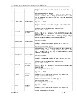
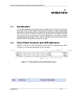
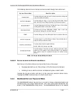
ON/OFF Switch
Two
–position pushbutton switch turns the source on and off.
WARNING!
OFF position does not remove AC input from
internal circuits. Disconnect external AC input before
servicing unit
2
OUTPUT ON/OFF Switch
Momentary switch that toggles the selected channel output power
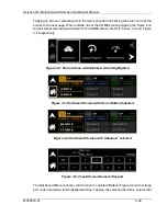
ON/OFF. Channel can be selected through front panel dashboard
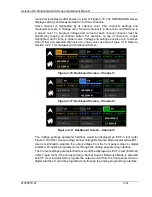
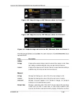
screen, refer Figure 3-16.
3
Display
TFT color graphics display with backlight and pressure-actuated
touch-screen.
menu-driven settings and functions.
4
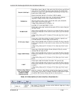
Rotary Encoder
Navigates between and within screens; scrolls through functions and
selects numerical values; adjusts output parameters in real-time.
5
Rotary Encoder Switch
Momentary-action switch that selects functions and enters numerical
values.
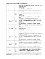
LED Mode Indicators
Indicates the mode that is active:
6
OUTPUT CH1
Output Channel 1 is turned on.
7
OUTPUT CH2
Output Channel 2 is turned on.
8
OUTPUT CH3
Output Channel 3 is turned on.
10
REM
Source is presently controlled by the remote digital interface. If the
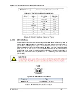
RS-232C, USB, GPIB or LAN interface is used, the REM state can be
enabled by the external controller using the SCPI command, SYST:REM.
Any time the REM LED is lit, the front panel control of the unit is
disabled. To regain control through the front panel, the external controller
must send the SCPI command, SYST:LOC.
11
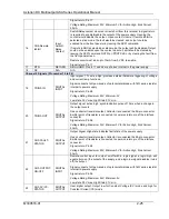
FAULT
Fault condition has occurred; output is shutdown, and output voltage is
programmed to zero.
Table 3-1: Front Panels controls and indicators
3.3
Basic Front Panel Operation
The Asterion DC Multioutput ASA Series power source provides extensive functionality
and programmability, which could be exercised through the front panel, and the remote
analog/digital control interface. This section provides basic details such as Navigation,
Menu selection, Rotary encoder and Soft numeric keyboard which are common to all
screens.
The Asterion DC Multioutput ASA Series power supply is shipped from the factory
configured for front panel (local) voltage/current/overvoltage Protection control, and with
the remote sense not connected (default to internal local voltage sensing at chassis output
terminals). The remote sense leads must be connected externally by the user to achieve
performance specifications. The external user interface connector (26 pin connector) is
supplied with a mating connector which has the remote inhibit input output ON/OFF control


