background image

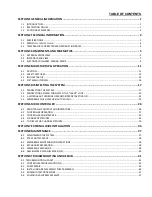
TABLE OF CONTENTS 

SECTION 1 GENERAL INFORMATION ............................................................................................... 1

1.1 INTRODUCTION .......................................................................................................................................................... 1
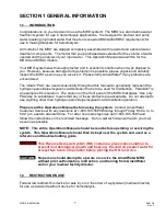
1.2 RESTRICTION ON USE ................................................................................................................................................. 1
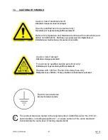
1.3 CAUTIONARY SYMBOLS .............................................................................................................................................. 2

SECTION 2 TECHNICAL INFORMATION............................................................................................. 3

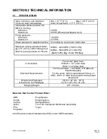
2.1 SPECIFICATIONS .......................................................................................................................................................... 3
2.2 MRO O

UTPUT 

W

ATER 

Q

UALITY

 ........................................................................................................................................ 4

2.3 TEMPERATURE CORRECTED MRO PRODUCTION RATES ............................................................................................. 4

SECTION 3 COMPONENTS AND SCHEMATICS .................................................................................. 5

3.1 EXTERNAL FRONT VIEW .............................................................................................................................................. 5

3.2 INTERNAL REAR VIEW ................................................................................................................................................. 7
3.3 ELECTRICAL DIAGRAM, MRO3 & MRO4 ..................................................................................................................... 9

SECTION 4 MRO STARTUP & OPERATION ...................................................................................... 11

4.1 CAUTION ................................................................................................................................................................... 11
4.2 SAFETY FEATURES ..................................................................................................................................................... 13

4.3 INITIAL STARTUP ....................................................................................................................................................... 14
4.4 SYSTEM SHUTDOWN ................................................................................................................................................ 16

SECTION 5 DISINFECTING THE SYSTEM .......................................................................................... 17

5.1 DISINFECTING THE SYSTEM ...................................................................................................................................... 17

5.2 DISINFECTING AN MRO CONNECTED TO A “LARGE” LOOP ....................................................................................... 23
5.3 A WORD ABOUT HYDROGEN PEROXIDE/PEROXYACETIC ACID ................................................................................. 24
5.4 MEMBRANE FLUSH FEATURE (AUTO FLUSH) ............................................................................................................ 25

SECTION 6 MRO CONTROLLER ...................................................................................................... 26

6.1 FRONT PANEL CONTROLS AND INDICATORS ............................................................................................................ 26

6.2 CONTROLLER OPERATION ........................................................................................................................................ 27
6.3 CONTROLLER ADJUSTMENTS.................................................................................................................................... 30
6.4 STANDARD SETPOINTS ............................................................................................................................................. 33
6.5 TO DISPLAY OR CHANGE SETPOINTS ......................................................................................................................... 35

SECTION 7 EXTERNAL WIRE INSTALLATION ................................................................................... 36
SECTION 8 MAINTENANCE ............................................................................................................ 37

8.1 MAINTAINING THE SYSTEM ...................................................................................................................................... 37

8.2 PT401 ANTI-SCALANT ............................................................................................................................................... 38
8.3 MEMBRANE MAINTENANCE INSTRUCTIONS ............................................................................................................ 38
8.4 EXCHANGE PREPERATION ........................................................................................................................................ 38

8.5 MEMBRANE EXCHANGE ........................................................................................................................................... 38
8.6 AMERIWATER CLEAN IN PLACE (CIP) ........................................................................................................................ 40

SECTION 9 TROUBLESHOOTING AND REPAIR ................................................................................. 41

9.1 TROUBLESHOOTING CHART ....................................................................................................................................... 41
9.2 CONTROLLER TROUBLESHOOTING ........................................................................................................................... 44

9.3 PUMP REPAIR ........................................................................................................................................................... 46
9.4 INSTALLING A REPLACEMENT PUMP ASSEMBLY ...................................................................................................... 46
9.5 SOLENOID TEST PROCEDURE .................................................................................................................................... 47
9.6 SOLENOID VALVE REPLACEMENT ............................................................................................................................. 47

Содержание MRO3

Страница 1: ...3 and MRO4 MANUAL 98 0140 Rev F MRO3 MRO4 OPERATION MAINTENANCE MANUAL FOR MODELS MRO3 AND MRO4 Manufactured With Pride In The USA www ameriwater com 800 535 5585 AmeriWater 3345 Stop 8 Rd Dayton OH 4...

Страница 2: ...ED TO A LARGE LOOP 23 5 3 A WORD ABOUT HYDROGEN PEROXIDE PEROXYACETIC ACID 24 5 4 MEMBRANE FLUSH FEATURE AUTO FLUSH 25 SECTION 6 MRO CONTROLLER 26 6 1 FRONT PANEL CONTROLS AND INDICATORS 26 6 2 CONTRO...

Страница 3: ...SECTION 10 WARRANTY 48 SECTION 11 MRO3 4 SPARE PARTS LISTING 49 11 1 ROUTINE REPLACEMENT ITEMS NON DURABLE COMPONENTS 51 ATTACHMENT 1 SUMMARY DISINFECTION PROCEDURE...

Страница 4: ...aution on the front panel of the MRO that states Use only PAA Use no substitutes means that any of these products are acceptable Do not attempt to use anything other than hydrogen peroxide peroxyaceti...

Страница 5: ...pour instructions et mesures de s curit Caution risk of danger Attention danger potentiel For service by qualified service personnel only Entretien par le personnel qualifi seulement Replace with 120...

Страница 6: ...of 150 psi MRO3 4200 GPD 15 897 LPD MRO4 5600 GPD 21 196 LPD Gallons Per Day Liters Per Day Connections Feed 3 4 plain hose Product 1 2 plain hose Drain 1 2 plain hose Electrical Requirements For the...

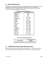
Страница 7: ...assium Fluoride Nitrate NO3 Sulfate Copper Barium Zinc Aluminum Arsenic Lead Silver Cadmium Chromium Selenium Mercury Antimony Beryllium Thallium 99 5 99 5 98 0 97 0 87 0 93 0 60 0 75 0 99 5 98 0 99 0...

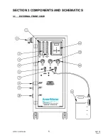
Страница 8: ...MRO 3 4 MANUAL 5 98 0140 Rev F SECTION 3 COMPONENTS AND SCHEMATICS 3 1 EXTERNAL FRONT VIEW...

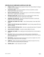
Страница 9: ...TAP WATER TEST PORT Valve for taking sample of feed water before the RO 7 PRODUCT WATER FOR DIALYSIS TEST PORT Valve for taking sample of Product Water For Dialysis 8 PRODUCT WATER FOR DIALYSIS Conne...

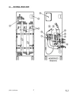
Страница 10: ...MRO 3 4 MANUAL 7 98 0140 Rev F 3 2 INTERNAL REAR VIEW...

Страница 11: ...e pump motor and protects the motor from overload 19 PRODUCT TO DRAIN SOLENOID Opens when water quality is below set point 20 SANITIZE SOLENOID ASSEMBLY Opens to allow the hydrogen peroxide peroxyacet...

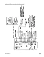
Страница 12: ...MRO 3 4 MANUAL 9 98 0140 Rev F 3 3 ELECTRICAL DIAGRAM MRO3 MRO4...

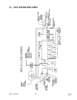
Страница 13: ...MRO 3 4 MANUAL 10 98 0140 Rev F 3 4 FLUID DIAGRAM MRO3 MRO4...

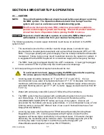
Страница 14: ...er strip that could cause low amperage 3 All local plumbing and electrical requirements should be met To avoid electrical shock always unplug the MRO system before opening the access panel or the face...

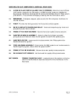
Страница 15: ...ll MRO fail safe modes will be disabled and damage to the MRO or injury to the patient may occur 12 Minimize the opportunities for bacterial growth between uses CAUTION To minimize bacterial growth op...

Страница 16: ...the membrane assemblies to avoid mix ups 3 INCOMING TAP WATER PRODUCT WATER FOR DIALYSIS and REJECT WATER TO DRAIN hoses are labeled to prevent incorrect connections 4 An audible alarm sounds whenever...

Страница 17: ...area of the barbed fitting 5 Connect the MRO INCOMING TAP WATER hose to the potable water supply using the Incoming Tap Water hose and fittings supplied If blending both warm and cold water to improv...

Страница 18: ...RO conductivity alarm may sound which is normal when the MRO is in FLUSH Press the ALARM SILENCE key on the MRO controller to silence the alarm The alarm will restart after a 3 minute delay 16 The con...

Страница 19: ...will cycle on some predetermine frequency to send the Product Water through the Divert to Drain feature of the MRO to the drain This will only occur when the Tank Full High limit switch indicates that...

Страница 20: ...d as one where all points in the loop can easily be disinfected by drawing less than 5 containers of PAA solution into the MRO and loop system If this can t be accomplished refer to section 5 1 b that...

Страница 21: ...cid concentrate or solution may cause severe chemical burns to the skin or eyes Additional information regarding the safe handling of PAA is found in this section on the Minncare or Renalin container...

Страница 22: ...bottom on the PAA Container continue holding the ENTER key but be prepared to release the ENTER key when the PAA container is emptied Approximately of the solution will remain in the bottom of the pla...

Страница 23: ...ability If the PAA at each water outlet has not been found to be positive at the minimum required amount another container must be drawn into MRO and into the loop until the minimum strength is tested...

Страница 24: ...ome residual PAA disinfecting solution is still in the system Less than 3 PPM of the disinfecting solution must be present before the system is reconnected to any dialysis machine 27 After rinsing wit...

Страница 25: ...ckmark on the log to verify that residual PAA tested negative 30 Disinfection is complete If the MRO was disconnected during disinfection from the loop or storage tank it can now be reconnected for us...

Страница 26: ...rposes of disinfecting and cleaning are distinctly different With disinfection exposure only to the disinfectant is required to destroy harmful bacteria On the other hand cleaning requires exposure by...

Страница 27: ...Slowly and carefully pour the disinfecting solution down the drain taking care to avoid spills splashes or breathing the vapors CAUTION Splashing PAA concentrate may cause severe chemical burns 4 Rins...

Страница 28: ...the drain rather than refill the storage tank FLUSH MODE 3 will cause all the water to be diverted to drain for each MEMBRANE AUTO FLUSH cycle On the other hand when an MRO is connected to a Direct Fe...

Страница 29: ...irst Setpoint RIGHT ARROW KEY Scrolls through Setpoints starting with last Setpoint UP ARROW KEY Increases value of Setpoint DOWN ARROW KEY Decreases value of Setpoint ENTER KEY Confirms entry of new...

Страница 30: ...DELAY 99 The unit is in the RO start delay The number is the seconds remaining before the RO pump starts OPERATING The RO unit is operating TANK FULL The unit is shut down due to a tank full condition...

Страница 31: ...w on the display When the tank level drops and the upper level switch clears the display will show TANK FULL 99 and the MRO unit will remain off The number is the tank full restart time and the number...

Страница 32: ...m and reset this delay PRETREAT If the pretreat input becomes active closes and stays active for 2 seconds the unit will shut down in a pretreat lockout condition PRETREAT will show on the display and...

Страница 33: ...ution Adjust the span adjustment for the correct reading If the cell is installed the unit can be calibrated by taking a sample from the PRODUCT TEST PORT and testing it with a known calibrated meter...

Страница 34: ...MRO 3 4 MANUAL 31 98 0140 Rev F FIGURE 6 2...

Страница 35: ...MRO 3 4 MANUAL 32 98 0140 Rev F FIGURE 6 3...

Страница 36: ...curs 0 99 Seconds 10 Auto Reset When a pressure fault shut down is active the system will attempt to restart after this delay If set to 0 system must be manually reset 0 99 minutes 0 Alarm Silence If...

Страница 37: ...E If this Set point is changed the unit must be recalibrated 0 6 1 C2 Range Selects range of TDS Conductivity monitor 0 50 1 100 2 250 3 500 4 1000 5 2500 6 5000 NOTE If this Set point is changed the...

Страница 38: ...nning Setpoint and the Right arrow key starts with the last Setpoint 3 The Up and Down arrow keys are used to increase or decrease the Setpoint value The value will change by 1 count each time a key i...

Страница 39: ...om outer shroud and remove inner terminals 3 Loosen the nut and run the float switch wires through the outer housing 4 Connect the High Tank float wires to contacts 1 6 Low Tank wires to contacts 2 7...

Страница 40: ...ually 5 Selection of water equipment for dialysis is the responsibility of the dialysis physician A water sample should be sent to a lab yearly for a complete AAMI water analysis to ensure that the pr...

Страница 41: ...and clean the membrane yourself Use the membrane to failure and replace 8 4 EXCHANGE PREPERATION 1 Turn off the MRO 2 Turn off the incoming tap water supply 3 Put a container under the CHLORAMINE TEST...

Страница 42: ...ough 7 9 If another membrane assembly is to be replaced repeat steps 1 through 8 IMPORTANT When the exchange is completed record the date the exchange was performed on the Startup Log Rinse Out Cycle...

Страница 43: ...the instructions in section 5 1 6 Pull an AAMI analysis The MRO can be used after disinfection when it begins producing water to the specifications 7 Reconnect the PRODUCT WATER hose to the dialysis...

Страница 44: ...Check MRO controller display for FAULT condition and correct the FAULT System has power but no water flow Feed source not open Feed pressure 20 PSI Incoming hose kinked Circuit board relay is not ope...

Страница 45: ...e the valve if it is defective see Section 9 6 Check PUMP PSI GAUGE to verify that it is within operating parameters Replace the pump assembly if necessary see Sections 9 3 and 9 4 Poor quality produc...

Страница 46: ...RO is operating Pump should be operating at 175 250 PSI Adjust Reject Water flow rate Check for restrictions in the PRODUCT WATER FOR DIALYSIS hose Check the feed pressure gauge on the dialysis machin...

Страница 47: ...yellow CPU active LED blinking If no is the green power LED DS1 Lit If no is the fuse OK If no replace the fuse If yes with a voltmeter verify power is applied to the power terminals L1 and L2 If pow...

Страница 48: ...or incorrect conductivity reading Is sensor wired correctly If yes is sensor installed inline as shown in the tubing diagram on page 18 If yes verify correct Conductivity range Range correct Does uni...

Страница 49: ...lamp or tie wrap securing the pump assembly and remove the assembly from the cabinet A new tie wrap is supplied with the replacement pump 7 Allow the pump assembly to fully drain before shipping warra...

Страница 50: ...ns 3 Press and hold the LEFT ARROW KEY and press the RIGHT ARROW KEY to access the DISINFECT MODE 4 Hold in the ENTER KEY until water flows to the drain If there is no water flow to the drain the sole...

Страница 51: ...kes government regulation materials shortages or other circumstances beyond its control To obtain warranty service notice must be given to the manufacturer within 30 days of the discovery of the defec...

Страница 52: ...MRO 3 4 MANUAL 49 98 0140 Rev F SECTION 11 MRO3 4 SPARE PARTS LISTING...

Страница 53: ...MRO 3 4 MANUAL 50 98 0140 Rev F...

Страница 54: ...Measuring High Range Paracetic Acid 97PX20501 Test Strips Renal Check 6 Bottles of 100 Strips each For Measuring Residual Peroxide 97PH20901 Test Strips pH 6 Bottles of 100 Strips each For Measuring...

Отзывы: