26
Rev. 5
Operation
Energizing Power Supply System Components
Note
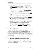
If turned off, the Model 430 Programmer must remain unpowered
for at least 5 seconds before it is powered back on. If not, there may
be an initialization error, in which case the following screen will be
displayed.
If this occurs, turn the Model 430 Programmer off, wait 15 seconds
or more, and power the Model 430 Programmer back on.
When powering the system off, first turn off the power supply controlled by
the Model 430 Programmer followed by the Model 430 Programmer. The
controller will then ensure the load sees no abnormal power transients as
the power supply is turning off.
3.1.2 Energizing
Power
Supply and Components
Warning
Do not change power supply jumpers, dip-switches, or other factory
settings. If not rack-mounted, always position power supply and
Model 601 Energy Absorber for convenience in disconnecting the
power cords.
3.1.2.1
Power Supply
Place the power supply switch in the ON position. No local (front
panel) adjustments or connections are required since the power
supply control mode and other parameters have been factory-
configured for control by the AMI Model 430 Power Supply
Programmer.
When powering the system off, turn OFF the power supply
before
powering off the Model 430 Programmer.
3.1.2.2
Zero Flux Current Transducer Power Supply
Caution
Operating the system without power applied to the current
transformer (CT) can will result in loss of control, and will probably
damage the CT.
The current transducer power supply is operational immediately
upon connection to a power receptacle. The supply must be
AMI Model 430 Programmer
FAILURE TO LOAD.
Содержание 05100PS-430-601
Страница 2: ......
Страница 10: ...x Rev 5 List of Figures ...
Страница 12: ...xii Rev 5 List of Tables ...
Страница 18: ...xviii Rev 5 Foreword Safety Summary ...
Страница 30: ...12 Rev 5 Introduction Operating Characteristics ...
Страница 42: ...24 Rev 3 Installation Power Up Procedure ...
Страница 114: ...96 Rev 5 Operation Summary of Operational Limits ...
Страница 119: ...Rev 5 101 Remote Interface Reference SCPI Command Summary LOCK ABsorber LOCK BRIGHTness LOCK NETsetup ...
Страница 156: ...138 Rev 5 Remote Interface Reference Error Messages ...
Страница 168: ...150 Rev 5 Service Return Authorization ...
Страница 190: ...172 Rev 5 Appendix Power Supply Details Figure A 3 Model 08150PS Dimensions Top and Side Views ...
Страница 220: ...202 Rev 5 Appendix Persistent Switch Operation Flowchart Figure A 17 Persistent Switch Operation Flowchart Page 3 ...
Страница 226: ...208 Rev 5 Index ...


