


Rev. 5
159
Appendix
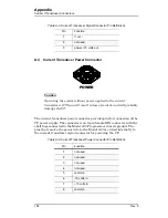
Quench I/O Connector
A.7
Aux Inputs Connector
The Aux Inputs connector provides pins for external voltage inputs,
reserved for future use. The shell lugs of the connector are connected to the
Model 430 Programmer chassis ground. The Aux Inputs connector is a
high density 15-pin D-sub female connector.
Each input pin has a 1 megohm resistor to analog circuit common. The
inputs are differential inputs. Aux Input 1 and Aux Input 2 have a ± 1 V
nominal input voltage range. Aux Input 3, Aux Input 4, Aux Input 5 and
Aux Input 6 have a ± 10 V nominal input voltage range.
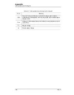
Table A-7.
Aux Inputs Connector Pin Definitions
Pin
Function
1
Aux Input 1 +
2
Aux Input 1 —
3
Aux Input 2 +
4
Aux Input 2 —
5
not used
6
Aux Input 3 +
7
Aux Input 3 —
8
Aux Input 4 +
9
Aux Input 4 —
10
not used
11
Aux Input 5 +
12
Aux Input 5 —
13
Aux Input 6 +
14
Aux Input 6 —
15
not used
Содержание 05100PS-430-601
Страница 2: ......
Страница 10: ...x Rev 5 List of Figures ...
Страница 12: ...xii Rev 5 List of Tables ...
Страница 18: ...xviii Rev 5 Foreword Safety Summary ...
Страница 30: ...12 Rev 5 Introduction Operating Characteristics ...
Страница 42: ...24 Rev 3 Installation Power Up Procedure ...
Страница 114: ...96 Rev 5 Operation Summary of Operational Limits ...
Страница 119: ...Rev 5 101 Remote Interface Reference SCPI Command Summary LOCK ABsorber LOCK BRIGHTness LOCK NETsetup ...
Страница 156: ...138 Rev 5 Remote Interface Reference Error Messages ...
Страница 168: ...150 Rev 5 Service Return Authorization ...
Страница 190: ...172 Rev 5 Appendix Power Supply Details Figure A 3 Model 08150PS Dimensions Top and Side Views ...
Страница 220: ...202 Rev 5 Appendix Persistent Switch Operation Flowchart Figure A 17 Persistent Switch Operation Flowchart Page 3 ...
Страница 226: ...208 Rev 5 Index ...