113335 - 12
www.amdry.com
11
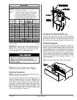
Exhaust Transition Piece
(Gas and Electric Only!)
Inside the tumbler of this dryer is an exhaust transition piece
that must be installed on the outlet of the exhaust before any
further venting is connected:
Remove the exhaust transition piece from the tumbler and
place it on the exhaust outlet.
Using the screws provided, secure the exhaust transition
piece to the dryer.
NOTE: It is recommended that this joint be taped as well
as all other duct joints to prevent moisture and lint from
escaping into the building.
WARNING
An exhaust duct transition piece is shipped inside of the
dryer’s tumbler and
MUST
be installed on the dryer’s
exhaust duct, with the hardware provided,
BEFORE
location venting is connected to the dryer.
THIS EXHAUST DUCT TRANSITION PIECE
MUST BE INSTALLED FIRST!
Failure to observe this installation requirement may result
in damage to the dryer, create a
FIRE HAZARD
and will
VOID
the manufacturer’s warranty.
012999JEV-GS/cj
P/N: 114092
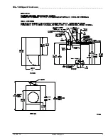
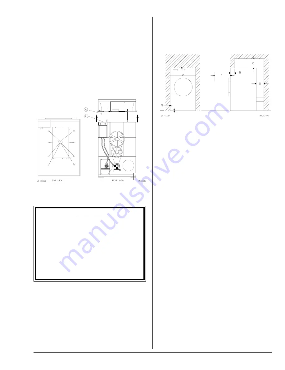
A
40-inches (101.6 cm) for optimum opening of load door.
B
The maximum thickness of the bulkhead is 4-inches (10.16 cm). For electric
dryers the maximum thickness of the bulkhead is 1-inch (2.54 cm) within
3-inches (7.62 cm) from the top of the control door.
C For gas and electric dryers a minimum overhead clearance of 12-inches
(30.48 cm) is required, providing no sprinkler is located above the dryer.
For steam dryers or if a sprinkler is located above the dryer, 18-inches
(45.72 cm) is required.
D Dryer should be positioned 24-inches (60.96 cm) away from the nearest
obstruction and 36-inches (91.44 cm) is recommended for ease of
installation, maintenance, and service.
E
2-inch (5.08 cm) minimum is required for opening the control door.
F
Flooring should be level or below dryer cabinet for ease of removing panels
during maintenance.
G Dryers may be positioned sidewall to sidewall, however a 1/16” (1.5875
mm) minimum allowance must be made for the opening and closing of the
control door, along with the removal of panels during maintenance.
Even though a 12-inch (30.48 cm) clearance is acceptable,
it is recommended that the rear of the dryer be positioned
approximately 2 feet (0.61 meters) from the nearest
obstruction (i.e., wall) for ease of installation, maintenance,
and service. Bulkheads and partitions should be made from
noncombustible materials. The clearance between the
bulkhead header and the dryer must be a minimum of
4-inches (10.16 cm) and must not extend more than 4-inches
(10.16 cm) to the rear of the front. The bulkhead facing must
not be closed in all the way to the top of the dryer. A 2-inch
(5.08 cm) clearance is required.
NOTE: Bulkhead facing should not be installed until after
the dryer is in place. Ceiling area must be located a
minimum of 12-inches (30.48 cm) above the top of the
dryer.
IMPORTANT: Even though a minimum of only 12-inches
(30.48 cm) is required, 18-inches (45.72 cm) or more is
suggested, for steam dryers and especially in cases where
sprinkler heads are over the dryers.
NOTE: When fire sprinkler systems are located above the
dryers, a minimum of 18-inches (45.72 cm) above the
dryer console (module) is suggested. Dryers may be
positioned side wall to side wall, however, 1- or 2-inches
(2.54 or 5.08 cm) is suggested for ease of installation and
maintenance. Allowances must be made for the opening
and closing of the control door and the lint door.
Dryer Enclosure Requirements _______
Bulkheads and partitions should be made of noncombustible
material.
NOTE: Allowances must be made for opening the control
door.
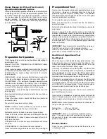
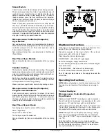
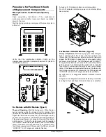
To Remove Top Console (Module)
Disconnect the ground wire (A) at the rear upper left hand
corner of dryer.
Remove the 8 sets of nuts and washers (B) holding the
console (module) to base.
Open the control door/control panel and disconnect the white
15-pin plug connector (C) (illustration below) located in the
base of the control box.
Disconnect white plug connector located outside backside
of the control box (provides power to heat circuit).
Lift the console (module) off the dryer base.
IMPORTANT: The dryer must be transported and handled
in an upright position at all times.
Содержание ML-130 III
Страница 28: ...ADC Part No 113335 12 07 31 08 5 ...


