20 Gear Drive, Plymouth Ind. Park, Terryville, CT 06786
Tel: (860) 585-1254 Fax: (860) 584-1973 http://www.amci.com
Networked Indexer/Driver User Manual
C
OMMAND
M
ODE
D
ATA
F
ORMAT
85
Input Data Format (continued)
Status Word 0 Format (continued)
Bit 4: At_Home –
Set to “1” when a homing command has completed successfully, “0” at all other times.
Bit 3: Stopped –
Set to “1” when the motor is not in motion. Note that this is stopped for any reason, not
just a completed move. For example, an Immediate Stop command during a move will set this bit to
“1”, but the Move_Complete Bit, (bit 7 above) will not be set.
Bit 2: In_Hold_State –
Set to “1” when a move command has been successfully brought into a Hold State.
Hold States are explained is the Controlling Moves In Progress section starting on page 22.
Bit 1: Moving_CCW –
Set to “1” when the motor is rotating in a counter-clockwise direction.
Bit 0: Moving_CW –
Set to “1” when the motor is rotating in a clockwise direction.
Status Word 1 Format
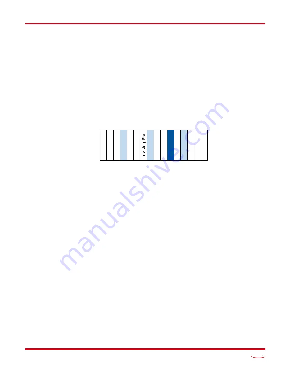
Figure R7.5 Command Mode: Status Word 1 Format
Bit 15: Drive_Is_Enabled –
Set to “1” when the motor driver section of the Networked Driver is enabled
and current is available to the motor. Set to “0” when the motor driver section is disabled. If this bit
is set to “1”, the motor current remains present when an E-Stop input is active. Motor current is
removed if there is a Driver_Fault (Bit 7 below) regardless of the state of this bit. Motor current is
also removed if the motor is idle and Idle Current Reduction is programmed to its
To 0%
setting.
Bit 14: Stall_Detected –
Set to “1” when a motor stall has been detected.
Bit 13: OUT1_State –
Present actual state of Output 1. When this bit is set to “1”, the output is in its on state
and conducts current.
Bit 12: Reserved Bit –
Will always equal zero.
Bit 11: Heartbeat_Bit –
This bit will change state approximately every 500 milliseconds. Monitor this bit to
verify that the unit and network connection are operating correctly. Note that this bit is only available
while the Networked Driver is in Command Mode.
Bit 10: Limit_Condition –
This bit is set if an End Limit Switch is reached during a move. This bit will be
reset when the Limit Switch changes from its active to inactive state, or when a Reset Errors Com-
mand is issued.
Bit 9: Invalid_Jog_Change –
Set during a Jog Move if parameters are changed to invalid values. Parame-
ters that can be changed during a Jog Move are Programmed Speed, Acceleration, and Deceleration.
Set while in Electronic Gearing mode if the Numerator or Denominator are set outside their range of
1 to 255.
Bit 8: Reserved –
Will always equal zero.
Status Word 1
15 14 13 12 11 10 09 08 07 06 05 04 03 02 01 00
Dri
v
e
_
Enabl
ed
Sta
ll_
Det
e
ct
ed
O
U
T
1_Sta
te
T
e
m
p
_90C
Conn
ect
_Lost
0
IN3Ac
ti
v
e
IN
2
_
A
c
tiv
e
IN
1
_
A
c
tiv
e
0
0
Dr
iv
er_F
aul
t
Li
mit
_
Cond
it
io
n
Hear
tbea
t_Bi
t
PL
C
_I
n_
PR
G
Содержание SD17060E2
Страница 1: ...MICRO CONTROLS INC ADVANCED U s e r M anual Manual 940 0S172 E2 Technology E2 Technology...
Страница 10: ...ABOUT THIS MANUAL Networked Indexer Driver User Manual ADVANCED MICRO CONTROLS INC 10 Notes...
Страница 22: ...UL CUL RECOGNIZED INSTALLATIONS Networked Indexer Driver User Manual ADVANCED MICRO CONTROLS INC 22 Notes...
Страница 54: ...CALCULATING MOVE PROFILES Networked Indexer Driver User Manual ADVANCED MICRO CONTROLS INC 54 Notes...
Страница 88: ...COMMAND MODE DATA FORMAT Networked Indexer Driver User Manual ADVANCED MICRO CONTROLS INC 88 Notes...
Страница 106: ...INSTALLING AN AMCI NETWORKED DRIVER Networked Indexer Driver User Manual ADVANCED MICRO CONTROLS INC 106 Notes...
Страница 130: ...ETHERNET IP EXPLICIT MESSAGING Networked Indexer Driver User Manual ADVANCED MICRO CONTROLS INC 130 Notes...
Страница 134: ...MODBUS TCP CONFIGURATION Networked Indexer Driver User Manual ADVANCED MICRO CONTROLS INC 134 Notes...
Страница 144: ...LEADERS IN ADVANCED CONTROL PRODUCTS ADVANCED MICRO CONTROLS INC...


