I
NSTALLING
AN
AMCI N
ETWORKED
D
RIVER
Networked Indexer/Driver User Manual
ADVANCED MICRO CONTROLS INC.
100
1.8 Connecting the Motor
1.8.1 Motor Connector
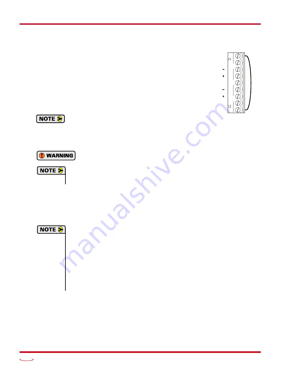
The motor connector is shown in figure T1.4. The two Interlock termi-
nals are a safety feature. When these two terminals are not connected, the
driver will not power the motor outputs, the Status LED turns on red, and
it activates the Fault Output. For normal operation, these two terminals
must be connected together with a short wire.
The two center tap pins, A CTAP and B CTAP, are there for wiring con-
venience only. They are electrically isolated from the rest of the driver
and are not used to power the motor. The
EARTH GND
pin is for the
shields of the motor cable. This pin is directly connected to the GND pin
of the power connector on the Networked Driver.
When powered, the motor connector represents a shock
hazard because it has 170/310 Vdc present on its termi-
nals. A rubber boot that is included with the connector
must be installed but is not shown in the following figures for clarity. When installing the
motor cable, slide the rubber boot onto the cable before wiring the connector. When you’re
sure the wiring is correct, slide the boot over the connector to cover the screw heads.
Always remove power from the Networked Driver before connecting or disconnecting
the motor.
1) Never connect the motor leads to ground or to a power supply.
2) Always connect the cable shield to the Earth Ground terminal of the Motor Connector on
the Networked Driver.
1.8.2 Interlock Wiring
The motor interlock is designed to prevent 170/310 Vdc power from being supplied to the motor connector
unless its mate is installed. As shown in figure T1.4 above, a short wire has to be installed between the two
outer pins of the mating connector or the motor will not receive power when it is plugged into the Networked
Driver.
It is possible to use the Interlock terminals as an alternative way of disabling motor current.
This is accomplished by wiring the two pins through a
mechanical contact
. The wires to the
Interlock pins should be kept as short as possible, which means using a mechanical relay in the
cabinet that houses the Networked Driver if you need to control the Interlock from a source
outside the cabinet. Only mechanical relays should be used. The voltage between the two
interlock pins will never exceed 5 Vdc, but 115/230 Vac may be present between either of the
two interlock pins and either of the power supply pins.
When the Networked Driver detects a break in the Interlock wiring, it will issue a
Driver Fault
error. This error is latched and can only be cleared after the interlock connection is re-estab-
lished. The fault can be cleared over the network by following the procedure outlined in
which starts on page 87 or by cycling power to the driver.
INTERLOCK
B CTAP
B
B
EARTH GND
A CTAP
INTERLOCK
A
A
Figure T1.4 Motor Connector with
Interlock Jumper
Содержание SD17060E2
Страница 1: ...MICRO CONTROLS INC ADVANCED U s e r M anual Manual 940 0S172 E2 Technology E2 Technology...
Страница 10: ...ABOUT THIS MANUAL Networked Indexer Driver User Manual ADVANCED MICRO CONTROLS INC 10 Notes...
Страница 22: ...UL CUL RECOGNIZED INSTALLATIONS Networked Indexer Driver User Manual ADVANCED MICRO CONTROLS INC 22 Notes...
Страница 54: ...CALCULATING MOVE PROFILES Networked Indexer Driver User Manual ADVANCED MICRO CONTROLS INC 54 Notes...
Страница 88: ...COMMAND MODE DATA FORMAT Networked Indexer Driver User Manual ADVANCED MICRO CONTROLS INC 88 Notes...
Страница 106: ...INSTALLING AN AMCI NETWORKED DRIVER Networked Indexer Driver User Manual ADVANCED MICRO CONTROLS INC 106 Notes...
Страница 130: ...ETHERNET IP EXPLICIT MESSAGING Networked Indexer Driver User Manual ADVANCED MICRO CONTROLS INC 130 Notes...
Страница 134: ...MODBUS TCP CONFIGURATION Networked Indexer Driver User Manual ADVANCED MICRO CONTROLS INC 134 Notes...
Страница 144: ...LEADERS IN ADVANCED CONTROL PRODUCTS ADVANCED MICRO CONTROLS INC...


