Commissioning
7.1.2.1
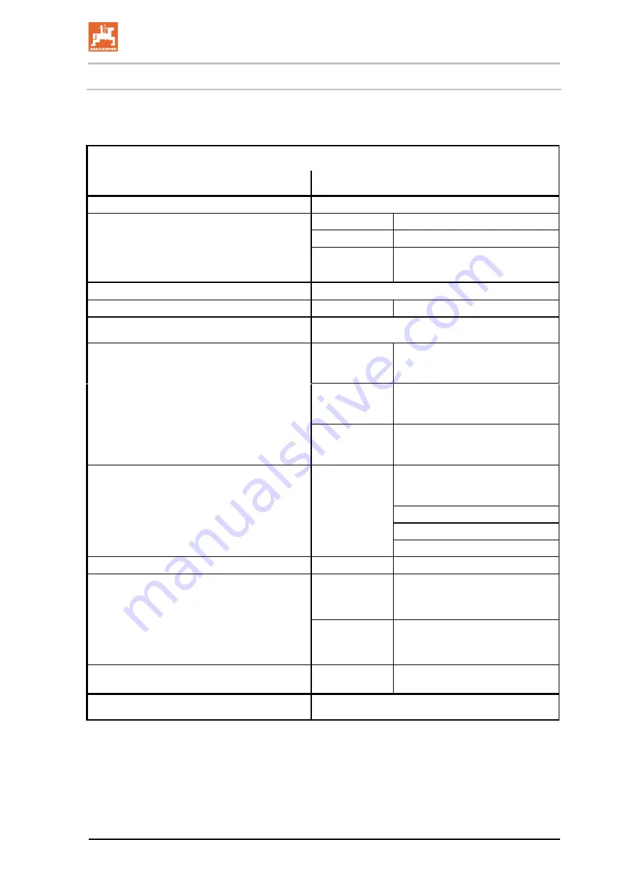
Combination options of coupling devices
The table shows the permitted combination options of coupling devic-
es for the tractor and implement.
Coupling device
Tractor
AMAZONE implement
Upper hitch
Pin coupling, form A, B, C
(ISO 6489-2)
Drawbar eye
Socket
Ø
40 mm
(ISO 5692-2)
A not automatically
Drawbar eye
Ø
40 mm
(ISO 8755)
B automatic
smooth pin
Drawbar eye
Ø
50 mm, only com-
patible with form A
(ISO 1102)
C automatic curved pin
Upper / lower hitch
Ball head coupling Ø 80 mm
(ISO 24347)
Ball coupling
Ø
80 mm
(ISO 24347)
Lower hitch
Towing hooks / hitch hooks
(ISO 6489-19)
Drawbar eye
Centre bore Ø
50 mm
Eyelet Ø 30 mm
(ISO 5692-1)
Swivel drawbar
eye
compatible only with
form Y, hole
Ø 50 mm,
(ISO 5692-3)
Drawbar eye
Centre bore Ø
50 mm
Eyelet Ø 30 - 41 mm
(ISO 20019)
Drawbar - Category 2
(ISO 6489-3)
Drawbar eye
Centre bore Ø
50 mm
Eyelet Ø 30 mm
(ISO 5692-1)
Socket
Ø
40 mm
(ISO 5692-2)
Ø
40 mm
(ISO 8755)
Ø
50 mm
(ISO 1102)
Drawbar
(ISO 6489-3)
Drawbar eye
(ISO 21244)
Drawbar / Piton-fix
(ISO 6489-4)
Drawbar eye
Centre bore Ø 50
mm
Eyelet Ø 30 mm
(ISO 5692-1)
Swivel drawbar
eye
compatible only with
form Y, hole
Ø 50 mm
(ISO 5692-3)
Yoke that cannot be rotated
(ISO 6489-5)
Swivel drawbar
eye
(ISO 5692-3)
Lower link hitch
(ISO 730)
Lower link traverse
(ISO 730)
BAG0021.14 05.19
135
Содержание UG 2200 Special
Страница 237: ...Liquid circuit 13 1 UG Special BAG0021 14 05 19 237 ...
Страница 238: ...Liquid circuit 13 2 UG Super 238 BAG0021 14 05 19 ...
Страница 242: ...Spray table Fig 182 242 BAG0021 14 05 19 ...
Страница 251: ...Spray table BAG0021 14 05 19 251 ...
Страница 252: ......


