Operating Manual
AMAZONE
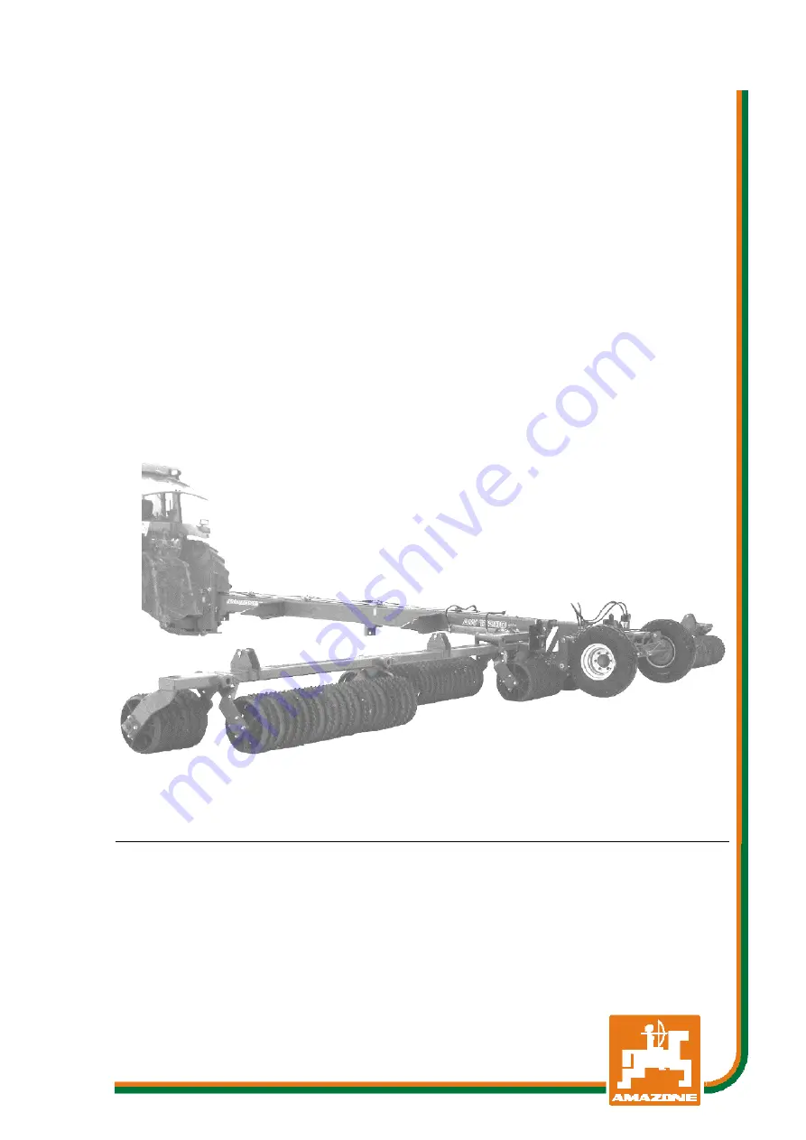
Land roller
AW 6600 / AW 7800 / AW 9400
AW 12200 / AW 15400
MG1433 BAG0030.4 02.17 Printed in Germany
Please read this operating
manual before first commis-
sioning.
Keep it in a safe place for
future use.
en
Страница 1: ...anual AMAZONE Land roller AW 6600 AW 7800 AW 9400 AW 12200 AW 15400 MG1433 BAG0030 4 02 17 Printed in Germany Please read this operating manual before first commis sioning Keep it in a safe place for future use en ...
Страница 2: ...son con cerned would not only harm himself but also make the mistake of blaming the machine for the reason of a possible failure instead of himself In order to ensure a good success one should go into the mind of a thing or make himself familiar with every part of the machine and to get acquainted with its handling Only this way you would be satisfied both with the machine as also with yourself To...
Страница 3: ...ss AMAZONEN WERKE H DREYER GmbH Co KG Postfach 51 D 49202 Tel E mail Hasbergen 49 0 5405 501 0 amazone amazone de Spare part orders Spare parts lists are freely accessible in the spare parts portal at www amazone de Please send orders to your AMAZONE dealer Formalities of the operating manual Document number MG1433 Compilation date 08 16 Copyright AMAZONEN WERKE H DREYER GmbH Co KG 2017 All rights...
Страница 4: ...s operating man ual and particularly the safety information Only after careful reading will you be able to benefit from the full scope of your newly purchased machine Please ensure that all the machine operators have read this operating manual before commissioning the machine Should you have problems or queries please consult this operating manual or give us a call Regular maintenance and timely r...
Страница 5: ...s working 21 2 16 Safety information for users 22 2 16 1 General safety and accident prevention information 22 2 16 2 Hydraulic system 25 2 16 3 Electrical system 26 2 16 4 Attached machines 26 2 16 5 Braking system 27 2 16 6 Tyres 28 2 16 7 Cleaning maintenance and repairs 28 3 Loading and unloading 29 4 Product description 30 4 1 Overview of subassemblies 30 4 2 Overview Supply lines between the...
Страница 6: ...ing the machine for transportation 62 9 Use of the machine 63 9 1 Preparing machine for working position 64 9 2 Turning area 65 10 Cleaning maintenance and repairs 66 10 1 Cleaning 66 10 2 Lubrication regulations 67 10 2 1 Lubricants 67 10 2 2 Lubrication point overview 68 10 3 Service plan overview 69 10 4 Axle and brake 70 10 4 1 Checking the brake drum for dirt 71 10 4 2 Draining the air reserv...
Страница 7: ...n the operating manual are always seen from the direction of travel 1 3 Diagrams used Handling instructions and reactions Activities to be carried out by the user are given as numbered instruc tions Always keep to the order of the handling instructions The reac tion to the handling instructions is given by an arrow Example 1 Handling instruction 1 Reaction of the machine to handling instruction 1 ...
Страница 8: ...o replace damaged warning pictograms If you still have queries please contact the manufacturer Obligations of the user Before starting work anyone charged with working with on the ma chine is obliged To comply with the basic workplace safety instructions and acci dent prevention regulations To read and understand the section General safety information of this operating manual To read the section W...
Страница 9: ... These shall be available to the operator at the latest on the comple tion of the contract Guarantee and liability claims for damage to peo ple or goods will be excluded if they can be traced back to one or more of the following causes Improper use of the machine Improper installation commissioning operation and mainte nance of the machine Operation of the machine with defective safety equipment o...
Страница 10: ...diate death or serious physical injury WARNING Indicates a medium risk which could result in death or serious physical injury if not avoided If the instructions are not followed then this may result in death or serious physical injury CAUTION Indicates a low risk which could incur minor or medium level physical injury or damage to property if not avoided IMPORTANT Indicates an obligation to specia...
Страница 11: ... 2 4 Safety and protection equipment Before each commissioning of the machine all the safety and protec tion equipment must be properly attached and fully functional Check all the safety and protection equipment regularly Faulty safety equipment Faulty or disassembled safety and protection equipment can lead to dangerous situations 2 5 Informal safety measures As well as all the safety information...
Страница 12: ...ll be considered as having been instructed if they have been instructed in the tasks they have to carry out and in the possible risks in the case of improper behaviour and also have been informed about the necessary protective equipment and measures 3 People with specialist technical training shall be considered as a specialist Due to their specialist training and their knowledge of the appropriat...
Страница 13: ...ut replacement work Check all the screw connections for a firm seat On completing maintenance work check the function of safety and protection equip ment 2 10 Constructive changes You may make no changes expansions or modifications to the ma chine without the authorisation of AMAZONEN WERKE This is also valid when welding support parts Any expansion or modification work shall require the written a...
Страница 14: ...ar and spare parts from third parties does not guaran tee that they have been constructed in a way as to meet the require ments placed on them AMAZONEN WERKE accepts no liability for damage arising from the use of non released spare parts wear parts or auxiliary materials 2 11 Cleaning and disposal Handle and dispose of any materials used carefully in particular When carrying out work on lubricati...
Страница 15: ...ms and other labels Warning pictograms The following diagrams show the arrangement of the warning picto grams on the machine Fig 1 Fig 2 Always keep all the warning pictograms of the machine clean and in a legible state Replace illegible warning pictograms You can obtain the warning pictograms from your dealer using the order number e g MD 075 ...
Страница 16: ... showing how to avoid the danger Warning pictograms explanation The column Order number and explanation provides an explanation of the neighbouring warning pictogram The description of the warning pictograms is always the same and specifies in the following order 1 A description of the danger For example danger of cutting 2 The consequence of nonobservance of the danger protection instructions For...
Страница 17: ...machine This danger will cause serious injuries anywhere on the body or death It is forbidden to ride on the machine and or climb the running machine This ban also applies to machines with treads or platforms Ensure that no one rides with the machine MD084 Risk of contusions over the whole body from machine parts moving down from above This danger will cause serious injuries anywhere on the body o...
Страница 18: ...ct a doctor immediately MD097 Danger of crushing your torso in the stroke range of the three point suspension due to the narrowing spaces when the three point hydraulic system is actuated This danger causes extremely serious injuries and even death Personnel are prohibited from entering the stroke area of the three point suspension when the three point hydraulics are actuated Only actuate the oper...
Страница 19: ... by lat erally swivelling machine parts This danger will cause serious injuries to the torso or death Maintain a sufficient safety distance between you and any moving machinery parts It is forbidden to stand in the swivel area of mov ing machine parts Ensure that all personnel maintain a sufficient safety distance from moving machine parts Instruct personnel to leave the swivelling area of any mov...
Страница 20: ...This danger can cause extremely serious and potentially fatal injuries Do not remain in the danger area between tractor and machine while the tractor engine is running and the tractor is not secured against unintentional rolling Instruct anyone in the danger area between tractor and machine to leave the danger ar ea while the tractor engine is running and the tractor is not secured against uninten...
Страница 21: ...on secured working areas Failure of important machine functions Failure of prescribed methods of maintenance and repair Danger to people through mechanical and chemical impacts Risk to environment through leakage of hydraulic fluid 2 15 Safety conscious working Besides the safety information in this operating manual the national general workplace safety and accident prevention regulations are bind...
Страница 22: ... the driving characteristics of the tractor and the connected machine Connecting and disconnecting the machine Only connect and transport the machine with tractors suitable for the task When connecting machines to the tractor three point hydraulic system the attachment categories of the tractor and the ma chine must always be the same Connect the machine to the prescribed equipment in accordance w...
Страница 23: ...k ensure that you understand all the equip ment and actuation elements of the machine and their function There is no time for this when the machine is already in opera tion Do not wear loose fitting clothing Loose clothing increases the risk over being caught by drive shafts Only start up the machine when all the safety equipment has been attached and is in the safety position Comply with the maxi...
Страница 24: ...ed brake delay for the loaded vehicle combination tractor plus connected machine Check the brake power before moving off When turning corners with the machine connected take the broad load and balance weight of the machine into account Before moving off ensure sufficient side locking of the tractor lower links when the machine is fixed to the three point hydrau lic system or lower links of the tra...
Страница 25: ...ake ο Take out the ignition key Have the hydraulic hose line checked at least once a year by a specialist for proper functioning Replace the hydraulic hose line if it is damaged or worn Only use original hydraulic hose lines The hydraulic hose lines should not be used for longer than six years including any storage time of maximum two years Even with proper storage and approved use hoses and hose ...
Страница 26: ...fety information is not followed ο In the case of retrofitting of electrical units and or compo nents on the machine with a connection to the on board power supply the user must check whether the installation might cause faults on the vehicle electronics or other com ponents ο Ensure that the retrofitted electrical and electronic compo nents comply with the EMC directive 2014 30 EU in the ap propr...
Страница 27: ...rt on the sealing rings on the hose couplings of the supply and brake lines Only move off with the machine connected when the pressure gauge on the tractor shows 5 0 bar Drain the air tank every day Before driving without the machine lock the hose couplings on the tractor Hang the hose couplings of the machine supply and brake lines in the appropriate empty couplings When filling up or replacing t...
Страница 28: ...nce and repair work on the machine when ο the drive is switched off ο the tractor engine is at a standstill ο the ignition key has been removed ο the connector to the machine has been disconnected from the on board computer Regularly check the nuts and bolts for a firm seat and retighten them as necessary If the machine or parts of the machine are raised secure them against unintentional lowering ...
Страница 29: ...oading as long as the tractor fulfils the power re quirements Compressed air brake system Only move off with the machine connected when the pressure gauge on the tractor shows 5 0 bar If the machine is to be loaded onto a transportation vehicle or unload ed from such a vehicle it must be coupled to a suitable tractor Loading For loading a person is required to help with manoeuvring Secure the mach...
Страница 30: ...Read this section when actually at the machine This helps you to understand the machine better The machine is composed of the following main components chassis frame rollers 4 1 Overview of subassemblies Fig 3 1 Chassis 2 Foldable arm 3 Arrester hook for securing machine arm during transportation 4 Rollers 5 Braking system 6 Chassis hydraulic cylinder 7 Hydraulic cylinder for folding mechanism ...
Страница 31: ...Towing crosspiece 2 Stand Fig 4 4 2 Overview Supply lines between the tractor and the machine Hydraulic hose lines Electric cable for lighting Air pressure braking system ο Brake line with coupling head yellow ο Supply line with coupling head red Fig 5 ...
Страница 32: ...uipment Fig 6 1 2 tail lights 2 brake lights 2 2 turn indicators required when the tractor turn indicator is obscured 3 2 warning signs square Fig 6 Fig 7 1 2 warning signs square 2 2 side lights Fig 7 Fig 8 1 2 x 3 reflectors yellow at the side max 3m apart Fig 8 ...
Страница 33: ...er points The danger area is the area around the machine in which people can be caught By work movements made by the machine and its tools By materials or foreign bodies thrown out of the machine By tools rising or falling unintentionally By unintentional rolling of the tractor and the machine Within the machine danger area there are danger points with perma nent or unexpected risks Warning pictog...
Страница 34: ...ting range underneath raised unsecured machines or parts of machines 4 6 Rating plate and CE marking The following diagrams show the location of the rating plate and CE marking The rating plate shows Vehicle machine ID no Type Basic weight kg Permissible support load kg Permissible rear axle load kg Permissible system pressure bar Permissible total weight kg Factory Model year Year of manufacture ...
Страница 35: ...asic weight kg 3950 3971 4350 7058 8738 Permissible axle weight kg 2400 2570 2780 3270 4000 Permissible supported weight kg 1550 1780 2020 2630 3800 Number of roller sections 3 5 5 7 7 Working speed km h 12 maximum Transportation speed km h 40 25 maximum Coupling point category Kat 2 5 3 5 Tyres 11 80 15 3 10 PR 15 0 55 17 10PR Air pressure bar 3 5 bar 3 0 bar Dual circuit service brake system yes...
Страница 36: ...IN 51524 The implement hydraulic fluid is suitable for the combined hydraulic fluid circuits of all standard tractor brands Control units 2 double action control units Operational brake system Dual circuit service brake sys tem 1 hose coupling red for the supply line 1 hose coupling yellow for the brake line Hydraulic brake system 1 hydraulic coupling conforms to ISO 5676 The hydraulic brake syste...
Страница 37: ...s suitable for rolling after sowing on light or heavy soils The whole of the surface is crumbled and reconsolidated which improves the flow of water to the seeded area The accumulation of waste grain and weed seeds after stubble pro cessing can also be improved by rolling For transportation the arms are swung alongside the frame The chassis and the tractor lower link hydraulics lift the machine in...
Страница 38: ...ing on the hydraulic function Latched for a permanent oil circulation Tentative activate until the action is executed Float position free oil flow in the control unit Folding using tractor con trol units Function Hose identification green Chassis Working position Double acting Transportation position green Fold rollers exter nally only AW15400 Fold out Double acting Fold in blue Rollers Fold out D...
Страница 39: ...erve the maximum approved hydraulic fluid pressure of 210 bar Only couple clean hydraulic connectors Push the hydraulic plug s into the hydraulic sockets until the hydraulic plug s is are felt to lock Check the coupling points of the hydraulic hose lines for a cor rect tight seat 1 Set tractor control unit to open centre position neutral position 2 Before coupling clean hydraulic plugs on hydrauli...
Страница 40: ... brake valve Fig 12 1 Supply line with coupling head red fas tened in the empty coupling as directed 2 Empty coupling for supply line 3 Brake line filter 4 Supply line filter Fig 12 Fig 13 1 Brake line with coupling head yellow fas tened in the empty coupling as directed 2 Empty coupling for brake line Fig 13 Fig 14 1 Trailer brake valve 2 Operating button for release valve only to be operated whe...
Страница 41: ...efore the first journey each day Only move off with the machine connected when the pressure gauge on the tractor shows 5 0 bar WARNING Risk of contusions cuts dragging catching or knocks from unintentionally rolling machine with the operating brake re leased Always couple the hose coupling of the brake line yellow first fol lowed by the hose coupling of the supply line red The operating brake of t...
Страница 42: ...leased Always uncouple the hose coupling of the supply line red first fol lowed by the hose coupling of the brake line yellow The operating brake of the machine only moves into the brake posi tion when the red hose coupling has been uncoupled Always keep to this order as otherwise the operating brake system will trip and may set the unbraked machine moving When the machine is uncoupled or pulled a...
Страница 43: ... the hydraulic screw union if present 2 Protect the hydraulic plug and hydraulic socket against soiling using the dust protection caps 3 Store the hydraulic hose line in the hose cabinet 5 4 3 Emergency brake In event of the machine being released from the tractor during travel the emergency brake will brake the machine Fig 16 1 Pulling cable 2 Brake valve with pressure accumulator 3 Hand pump to ...
Страница 44: ...s hydraulic oil into the brake and decelerates the implement or into the hose line to the tractor and impedes the coupling of the brake line to the tractor In these cases relieve pressure using the hand pump on the brake valve 5 5 Parking brake When the parking brake is on it secures the uncoupled machine against unintentional rolling The parking brake is operated by turning the crank which in tur...
Страница 45: ...ther vehicle parts When the parking brake is off the bowden cable must be slightly slack 5 6 Safety chain for implements without brake system Implements without a brake system or with a single line brake system must be equipped with a safety chain in compliance with local country regulations The safety chain must be correctly fixed to a suitable position on the tractor before transporting Fig 19 ...
Страница 46: ... the surface of the soil Fig 20 The AW 15400 rollers have outside rollers which can be folded up vertically for transportation by road Fig 21 For transportation by road fold up the outer roll ers and use the transportation bolt Fig 22 1 to lock them onto the pin Fig 22 2 Secure with spring clip Fig 22 3 When the machine is in use fasten the transpor tation bolt to the pin of an outer roller Fig 22...
Страница 47: ...d the machine have the same attachment category 5 9 Stand Stand raised when in use or during trans portation Stand lowered when the machine is uncou pled Fig 24 1 Raising and lowering stand Fig 24 1 1 Release spring clip Fig 24 3 2 Pull out pin Fig 24 2 3 Raise lower stand 4 Peg stand with pin and secure with spring clip Fig 24 WARNING Risk of crushing fingers when oper ating the stand ...
Страница 48: ...sure mechanism consists of a pressure spring which is pretensioned with a screw Adjusting the pressure mechanism 1 Loosen both lock nuts Fig 25 2 2 Tighten screw Fig 25 3 Increase pressure on roller sections Undo screw Reduce pressure on roller sections 3 Retighten lock nuts Fig 25 5 11 Shuttle valve option For information on switching hydraulic functions on tractors with only one double action co...
Страница 49: ...tor which is suitable for the task The tractor and machine must meet the national road traffic regulations The operator and the user shall be responsible for compliance with the statutory road traffic regulations WARNING Risk of contusions cutting catching drawing in and knocks in the area of hydraulically or electrically actuated components Do not block the operator controls on the tractor which ...
Страница 50: ...ractor must always be subjected to at least 20 of the dead weight of the tractor The tractor must achieve the brake delay specified by the tractor manufacturer even with the machine connected 6 1 1 Calculating the actual values for the total tractor weight tractor axle loads and load capacities as well as the minimum ballast The approved total tractor weight specified in the vehicle documenta tion...
Страница 51: ...1 a2 See technical data of tractor and front ma chine mounting or front weight or measure ment a1 m Distance from the centre of the front axle to the centre of the lower link connection See tractor operating manual or measure ment a2 m Distance between the centre of the lower link connection point and the centre of gravi ty of the front machine mount or front weight centre of gravity distance See ...
Страница 52: ... tractor operating manual in the table Section 6 1 1 7 6 1 1 4 Calculation of the actual total weight of the combined tractor and machine H L V tat F T G G Enter the numeric value for the calculated actual total weight and the approved total tractor weight specified in the tractor operating manual in the table Section 6 1 1 7 6 1 1 5 Calculation of the actual rear axle load of the tractor TH tat t...
Страница 53: ...ation papers The actually calculated values must be less than or equal to the permissible values WARNING Risk of contusions cutting catching drawing in and knocks through insufficient stability and insufficient tractor steering and brake power It is forbidden to couple the machine to the tractor used as the basis for calculation if One of the actual calculated values is greater than the approved v...
Страница 54: ...ο that the tractor s actual static rear axle weight does not ex ceed the permissible rear axle weight ο that the permissible total weight of the tractor is observed ο that the approved load capacities of the tractor tyres are not exceeded 6 1 3 Machines without their own brake system WARNING Risk of contusions cuts dragging catching or knocks from insufficient tractor brake power The tractor must ...
Страница 55: ...tractor engine is running with the Cardan shaft hydraulic system connected ο if the ignition key is in the tractor and the tractor engine can be started unintentionally with the Cardan shaft hydraulic system connected ο if the tractor and machine have not each been prevented from unintentionally rolling away by applying their parking brakes and or securing them with wheel chocks ο if moving parts ...
Страница 56: ... the machine Only actuate the operator controls for the tractor s three point hydrau lic system from the intended workstation if you are outside of the danger area between the tractor and the machine 7 1 Coupling the machine WARNING Danger of breaking during operation insufficient stability and insufficient tractor steering and braking power on improper use of the tractor You may only connect the ...
Страница 57: ...and lower link pins if there are clear signs of wear Use a lynch pin on each of the upper and lower link pins in the pivot points on the three point frame attachment to secure them against unintentional release WARNING Risk of energy supply failure between the tractor and the ma chine through damaged power lines During coupling check the course of the power lines The power lines must give slightly...
Страница 58: ...the tractor s PTO shaft is switched off 4 4 Connect the supply lines to the tractor 4 5 Position the lower link hooks so that they are aligned with the lower linking points on the machine 5 Now reverse the tractor further towards the machine so that the tractor s lower link hooks automatically pick up the ball linings on the machine s lower pivot points The lower link hooks lock automatically 6 Ra...
Страница 59: ...ine if necessary 1 Park the machine in a level parking area on solid ground 2 Uncouple the machine from the tractor 2 1 Secure the machine against unintentionally rolling away See page 55 2 2 Lower stand 2 3 Release lower link 2 4 From the tractor seat unlock lower link hooks and uncou ple 2 5 Pull tractor forward approx 25 cm This will allow more room between tractor and machine and give better a...
Страница 60: ... the air reservoir falls to less than 3 bar e g through repeated operation of the release valve or because of leaks in the braking system To release the service brake fill the air reservoir remove all air from the braking system at the drain valve on the air reservoir 1 Connect machine to the manoeuvring vehicle 2 Brake the manoeuvring vehicle 3 Remove wheel chocks 4 Pull out release valve to the ...
Страница 61: ...of contusions cutting catching drawing in and knocks when making interventions in the machine through unintentional machine movements On folding machines check that the transport locks are locked correctly Secure the machine against unintentional movements before starting transportation WARNING Risk of contusions cuts dragging catching or knocks from tipping and insufficient stability Drive in suc...
Страница 62: ...unit green Fold in the arms by rolling the rollers away on the ground Fig 29 Adjust the height of the machine with tractor control unit and the tractor lower link hydraulic system in such a way that when the arms are folded in they lock in the transportation position Fig 28 1 Slow reversing makes it easier to roll off the rollers during the folding operation WARNING AW 15400 Secure the outer rolle...
Страница 63: ...ctor with the attached machine In so doing take your personal abilities into account as well as the road traffic visibility and weather conditions the driving characteris tics of the driver and the connected machine WARNING Risk of being crushed cut caught drawn in or struck if the ma chine is unintentionally released from its attached or hitched position Each time before the machine is used carry...
Страница 64: ...er the machine completely Transportation lock Fig 31 1 unlocked 3 Actuate tractor control unit green Fold out the arms by rolling the rollers away on the ground Fig 31 Only AW 15400 4 Open the stop tap of the running gear cylin der Position 1 Hydraulic function of the outer rollers is switched on 5 Actuate tractor control unit green The outer rollers fold down Fig 32 Driving slowly forwards makes ...
Страница 65: ...Use of the machine AW BAG0030 4 02 17 65 9 2 Turning area CAUTION When turning the machine must be left in the working position The frame can be damaged by lifting the rollers from the working position ...
Страница 66: ...ning Pay particular attention to the brake air and hydraulic hose lines Never treat brake air and hydraulic hose lines with benzene benzole petroleum or mineral oils After cleaning grease the machine in particular after cleaning with a high pressure cleaner steam jet or liposoluble agents Observe the statutory requirement for the handling and removal of cleaning agents Cleaning with a high pressur...
Страница 67: ...rication points and grease gun before lubrication so that no dirt is pressed into the bearings Press the dirty grease out of the bearings completely and replace it with new grease Fig 34 10 2 1 Lubricants For lubrication work use a lithium saponified multipurpose grease with EP additives Company Lubricant name Normal operating condi tions Extreme operating con ditions ARAL Aralub HL 2 Aralub HLP 2...
Страница 68: ...uantity 1 Arm pivot point 100 2 2 Roller flange bearings 100 10 14 3 Roller sections 100 4 6 4 Chassis attachment 100 2 Chassis hydraulic cylinder 100 2 6 Towing crosspiece 100 1 above Fig Outer roller pivot point AW15400 100 2 Axle Lubrication point Interval h Quantity 1 Wheel hub bearings 200 2 2 Camshaft 100 2 3 Cam bearing 100 2 ...
Страница 69: ...tness 69 X Daily Component Servicing work see page Workshop work Air reservoir Drain 71 Weekly every 50 working hours Component Servicing work see page Workshop work Hydraulic system Inspection for defects 76 X Wheels Check air pressure 74 Every three months 200 working hours Component Servicing work see page Workshop work Dual circuit service brake system Inspection according to check instruction...
Страница 70: ...ly be carried out by trained specialist personnel Special care is required for welding torch cutting and drill ing work in the vicinity of brake lines Always carry out a braking test after any adjusting or repair work on the braking system General visual inspection WARNING Carry out a general visual check of the brake system Observe and check the following criteria Pipe lines hose lines and couple...
Страница 71: ...st be removed 10 4 2 Draining the air reservoir 1 Use the ring to keep the drain valve Fig 37 1 pulled sideways until no more water flows out of the air reservoir Water flows out of the drain valve 2 Unscrew the drain valve from the air reser voir and clean the air reservoir if you find dirt deposits Fig 37 10 4 3 Cleaning the line filter Clean the two line filters Fig 38 every 3 months more frequ...
Страница 72: ... pressure 1 Connect a pressure gauge to the test connection on the brake cylinder Set value with brake not applied 0 0 bar 4 Visual inspection of brake cylinder 1 Check the dust sleeves or gaiters for damage 2 Replace damaged parts 5 Joints on brake valves brake cylinders and brake linkages Joints on brake valves brake cylinders and brake linkages must move freely Grease or lightly oil if necessar...
Страница 73: ...in hole On match turn it to the next hole max 30 5 Fit split pin and bend slightly open 6 Reload dust cap with high melting point grease and drive it into or screw it onto the wheel hub 10 4 7 Setting the linkage adjuster workshop work When the brake is applied the brake cylinder stroke must be no more than 10 to 50 of the total brake cylinder stroke If it is more than 50 the linkage adjuster must...
Страница 74: ...ls Tyre fitting requires sufficient skills and proper assembly tools Use the jack only at the jacking points indicated 10 5 1 Tyre pressures The required tyre pressure is dependent on ο tyre size ο tyre load rating ο speed of travel The operational performance of the tyres is reduced ο by overloading ο if tyre pressure is too low ο if tyre pressure is too high Check tyre pressures regularly when t...
Страница 75: ...rrosion from the wheel rim seating surfaces before fitting a new another tyre Corrosion can cause damage to the wheel rims when the vehicle is in operation When fitting new tyres always use new valves for tubeless tyres or new inner tubes Always fit the valves with valve caps which have a gasket insert ...
Страница 76: ...e trailer Ensure that the hydraulic hose lines are connected correctly Regularly check all the hydraulic hose lines and couplings for damage and impurities Have the hydraulic hose line checked at least once a year by a specialist for proper functioning Replace the hydraulic hose line if it is damaged or worn Only use original AMAZONE hydraulic hose lines The hydraulic hose lines should not be used...
Страница 77: ... Replace any worn or damaged hydraulic hose lines immediately 10 6 3 Inspection criteria for hydraulic hose lines For your own safety comply with the following inspection criteria Replace hydraulic hose lines on determining any of the follow ing during the inspection Damage to the outer layer up to the ply e g scouring points cuts cracks Brittleness of the outer layer crack formation of the hose m...
Страница 78: ...is no tension apart from the hose s own weight ο There is no possibility of jolting on short lengths ο Outer mechanical influences on the hydraulic hose lines are avoided Use appropriate arrangements and fixing to prevent any scouring of the hoses on components or on each other If necessary secure hydraulic hose lines using protective co vers Cover sharp edged components ο The approved bending rad...
Страница 79: ...rom the tractor Visually check the upper and lower link pins for obvious defects whenever the machine is coupled Replace the towing crosspiece if there are clear signs of wear 10 8 Electrical lighting system Changing bulbs 1 Unscrew safety lens 2 Remove defective bulb 3 Insert replacement bulb make sure voltage and wattage is cor rect 4 Fit safety lens and screw on ...
Страница 80: ...Cleaning maintenance and repairs 80 AW BAG0030 4 02 17 10 9 Hydraulics diagram Fig 41 ...
Страница 81: ...5 315 380 M 18 27 290 405 485 M 18x1 5 325 460 550 M 20 30 410 580 690 M 20x1 5 460 640 770 M 22 32 550 780 930 M 22x1 5 610 860 1050 M 24 36 710 1000 1200 M 24x2 780 1100 1300 M 27 41 1050 1500 1800 M 27x2 1150 1600 1950 M 30 46 1450 2000 2400 M 30x2 1600 2250 2700 M M4 M5 M6 M8 M10 M12 M14 M16 M18 M20 M22 M24 2 4 4 9 8 4 20 6 40 7 70 5 112 174 242 342 470 589 Coated bolts have different tighteni...
Страница 82: ... 49 0 5405 501 0 e mail amazone amazone de http www amazone de Plants D 27794 Hude D 04249 Leipzig F 57602 Forbach Branches in England and France Manufacturers of mineral fertiliser spreaders field sprayers sowing machines soil cultivation ma chines and communal units ...