


Chapter 6: IP Core Interfaces
6–7
Avalon-ST RX Interface
June 2012
Altera Corporation
Stratix V Hard IP for PCI Express
f
For more information about the Avalon-ST protocol, refer to the
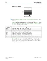
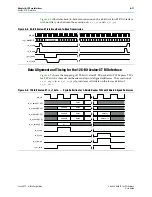
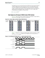
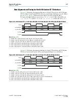
Data Alignment and Timing for the 64-Bit Avalon-ST RX Interface
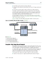
To facilitate the interface to 64-bit memories, the Stratix V Hard IP for PCI Express
aligns data to the qword or 64 bits by default; consequently, if the header presents an
address that is not qword aligned, the Hard IP block shifts the data within the qword
to achieve the correct alignment.
Figure 6–2
shows how an address that is not qword
aligned, 0x4, is stored in memory. The byte enables only qualify data that is being
written. This means that the byte enables are undefined for 0x0–0x3. This example
corresponds to
. Qword alignment applies to all types of
request TLPs with data, including memory writes, configuration writes, and I/O
writes. The alignment of the request TLP depends on bit 2 of the request address. For
completion TLPs with data, alignment depends on bit 2 of the
lower
address
field.
This bit is always 0 (aligned to qword boundary) for completion with data TLPs that
are for configuration read or I/O read requests.
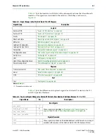
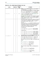
rx_st_be
(deprecated)
8,
16, 32
O
component
specific
Byte enables corresponding to the
rx_st_data
. The byte
enable signals only apply to PCI Express TLP payload fields.
When using 64-bit Avalon-ST bus, the width of
rx_st_be
is 8
bits. When using 128-bit Avalon-ST bus, the width of
rx_st_be
is 16 bits. When using a 256-bit Avalon-ST bus, the
width of
rx_st_be
is 32 bits. This signal is optional. You can
derive the same information by decoding the
FBE
and
LBE
fields
in the TLP header. The byte enable bits correspond to data
bytes as follows:
rx_st_data[63:56]
=
rx_st_be[7]
rx_st_data[55:48]
=
rx_st_be[6]
rx_st_data[47:40]
=
rx_st_be[5]
rx_st_data[39:32]
=
rx_st_be[4]
rx_st_data[31:24]
=
rx_st_be[3]
rx_st_data[23:16]
=
rx_st_be[2]
rx_st_data[15:8]
=
rx_st_be[1]
rx_st_data[7:0]
=
rx_st_be[0]
This signal is deprecated.
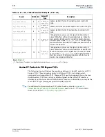
rx_st_parity
8,
16, 32
O
component
specific
Byte parity is generated when you turn on
Enable byte parity
ports on Avalon-ST interface
on the
System Settings
tab of the
GUI.
Each bit represents odd parity of the associated byte of the
rx_st_data
bus. For example,, bit[0] corresponds to
rx_st_data[7:0]
, bit[1] corresponds to
rx_st_data[15:8]
, and so on.
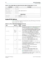
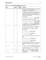
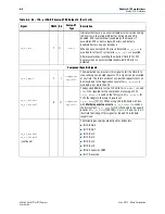
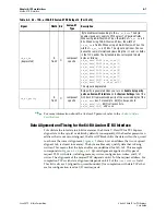
Table 6–3. 64-, 128-, or 256-Bit Avalon-ST RX Datapath (Part 4 of 4)
Signal
Width
Dir
Avalon-ST
Type
Description