background image


Altai Technologies Ltd. All rights reserved 


C1n Series WIFI AP/CPE Web-admin Configuration Manual 


TPS15-003_rev1.3 

Syslog severity

: Specify which severity level of log that C1n sends to remote syslog 

server. The severity options are listed in Table 6-1. 
 

6.3.


SNMP Setting 

 
Simple Network Management Protocol (SNMP) is a Network management protocol 
used almost exclusively in TCP/IP networks. SNMP provides a means to monitor and 
control network devices, and to manage configurations, statistics collection, 
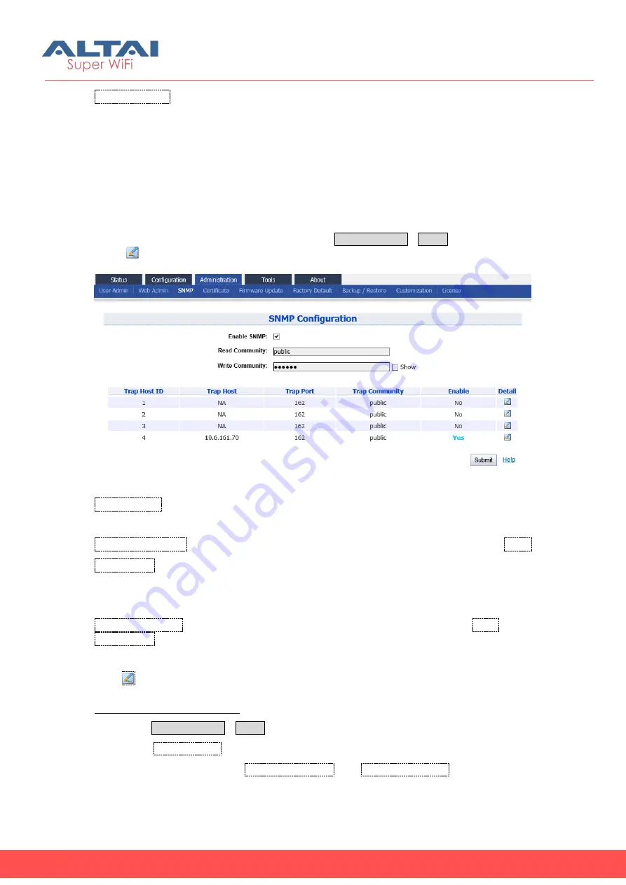
performance, and security. C1n supports SNMP protocol that user may use ALTAI 
Wireless Management System (AWMS) or a third party NMS to manage C1n Series 
AP/CPE. User may specify the SNMP setting via 

Administration

SNMP

. Also user may 

click “

” to specify the SNMP manager if necessary. 


Figure 6-3 SNMP Configuration 


Enable SNMP

: Enable or Disable SNMP in C1n; if enabled, C1n communicates with 

AWMS or others NMS. By default, it is “Enabled”. 

Read  Community

:  Specify  read  community  of  SNMP  protocol;  the  string  of 

Read 

Community

  between  NMS  and  C1n  must  be  identical.  If  the  community  string  is 

correct,  C1n  responds  with  the  requested  information  from  NMS;  otherwise,  C1n 

simply discards the request and does not respond. The default setting is “public” 

Write Community

: Specify write community of SNMP protocol; the string of 

Write 

Community

 between NMS and C1n must be identical. If the community string is 

correct, NMS can modify C1n configuration; C1n simply discards the request and 
does not respond. The default setting is “netman”. 
Press 

To edit Trap Host 


Enable SNMP function in C1n:  

1.


Select 

Administration

SNMP


2.


Check 

Enable SNMP

 to enable SNMP protocol 

3.


Specify the string in both 

Read Community

 and 

Write Community

 that are 

identical in the NMS’s setting. 

Содержание C1AN

Страница 1: ...Altai Technologies Ltd All rights reserved ALTAI C1N SERIES WIFI AP CPE WEB ADMIN CONFIGURATION MANUAL Version 1 3 Date January 2016 ...

Страница 2: ...ed or operating in conjunction with any other antenna or transmitter Interference Statement This equipment has been tested and found to comply with the limits for a Class B digital device pursuant to Part 15 of the FCC Rules These limits are designed to provide reasonable protection against harmful interference in a residential installation This equipment generates uses and can radiate radio frequ...

Страница 3: ...g The user is advised to keep away from the base station and antenna with at least 45cm when the base station is in operation Please install a lightning arrestor to protect the base station from lightning dissipation during rainstorms Lightning arrestors are mounted outside the structure and must be grounded by means of a ground wire to the nearest ground rod or item that is grounded Disclaimer Al...

Страница 4: ... 4 2 1 1 4 WLAN 20 4 2 1 1 5 Association List 21 4 2 1 2 Radio0 Interface Status Station Mode 23 4 2 1 2 1 Status 23 4 2 1 2 2 Statistic 24 4 2 1 2 3 Channel usage 24 4 2 1 2 4 STA Info 24 4 2 1 2 5 AP Info 25 4 2 1 3 Radio0 Interface Status Repeater Mode 25 4 2 1 3 1 Status 26 4 2 1 3 2 Statistic 26 4 2 1 3 3 Channel usage 26 4 2 1 3 4 STA Info 27 4 2 1 3 5 AP Info 27 4 2 1 3 6 WLAN 27 4 2 1 3 7 ...

Страница 5: ...1 WLAN 0 GENERAL CONFIGURATION 84 5 4 1 2 2 2 WLAN 0 SECURITY 87 5 4 1 2 2 3 WLAN 0 QOS 87 5 4 1 3 RADIO0 CONFIGURATION REPEATER MODE 88 5 4 1 3 1 GENERAL CONFIGURATION 88 5 4 1 3 2 WLAN CONFIGURATION 89 5 4 1 3 2 1 REPEATER CONFIGURATION 91 5 4 1 3 2 2 WLAN CONFIGURATION 91 5 4 1 4 RADIO0 CONFIGURATION BRIDGE MODE FOR C1AN AND C1XAN 92 5 4 1 4 1 GENERAL CONFIGURATION 92 5 4 1 4 2 STATIC BRIDGE SE...

Страница 6: ...ts reserved C1n Series WIFI AP CPE Web admin Configuration Manual TPS15 003_rev1 3 12 1 1 Ping to Host 115 12 1 2 Traceroute to Host 116 7 3 WATCHDOG 117 7 3 1 SCHEDULE REBOOT 117 7 3 2 PING WATCHDOG 119 8 C1N SERIES INFORMATION 119 ...

Страница 7: ... brackets are optional parameters or values that the user can choose to specify or omit Within commands item enclosed in braces are options which the user must choose from Within commands the vertical bar separates options An ellipsis indicates a repetition of preceding parameter The right angle bracket separates successive menu selection NOTE This message denotes neutral or positive information t...

Страница 8: ...duct name Model No Hardware Version Firmware Version C1n WA1011N G Above V1 1 1 2 6 x C1an WA1011N A Above V1 1 1 2 6 x C1xn WA1011N GX Above V1 1 1 2 6 x C1xan WA1011N AX Above V1 1 1 2 6 x Table 2 1 C1n Series Model 3 Getting Started 3 1 Setup Local Area Connection on Your PC C1n Series AP CPE can be connected to your PC in wired mode or in wireless mode In the following wired mode will be intro...

Страница 9: ...ights reserved C1n Series WIFI AP CPE Web admin Configuration Manual TPS15 003_rev1 3 Figure 3 1 Control Panel in Windows XP 3 Right click the Local Area Connection and select Properties Figure 3 2 Network Connection in Windows XP ...

Страница 10: ...Mark the Internet Protocol TCP IP and click Properties 6 Type in an IP address for example 192 168 1 2 which is under the same subnet as the Default IP Address of C1n Series AP CPE 192 168 1 222 7 Using the default Subnet mask default 255 255 255 0 setting in the first time 8 Keep the Default gateway as Blank 9 Keep the Preferred DNS server and Alternate DNS server as Blank also 10 Click OK when y...

Страница 11: ...E and your PC have a correct connection NOTE Using the same PC to ping different C1n Series AP CPE may cause ping failure This is because C1n Series AP CPE has the same default IP address but different MAC addresses You need to type command arp d in Command Prompt to clear ARP table on PC before each ping 3 3 Configuration with Web Admin The C1n Series AP CPE can be accessed through a Web Browser ...

Страница 12: ...case sensitive 3 Other level account guest for only view is shown in Table3 1 also With this view only account the user only can view the configuration of C1n but no change right Firmware version Default User Name Default Password 1 2 6 x admin admin 1 2 6 x guest guest Table 3 1 C1n Series default User Name and Password Figure 3 5 C1n Series AP CPE web login page 4 A home page in IE appears as sh...

Страница 13: ...Secondary IP Address 192 168 99 110 6E HEX 110 DEC The secondary IP shall use IP address from 192 168 99 5 to 192 168 99 254 The other IP addresses are reserved If the last byte of the MAC address matches the reserved IP addresses the supported device shall follow the following MAC to IP address mapping Ethernet MAC address Reserved Purpose Replaced MAC byte Secondary IP address XX XX XX XX XX 00 ...

Страница 14: ...erface is separated to 5 levels Level 1 menu Level 2 menu Interface selection Level 3 menu and Configuration options Figure 3 7 C1n Series Webpage 3 6 Logout from C1n Series Web Page On the top right corner of C1n Series AP CPE web interface click Logout button to logout from C1n Series On the other side you can directly close C1n Series AP CPE webpage to logout from C1n Series Figure 3 8 Logout 3...

Страница 15: ...rmation Historical Statistics information and Log information 4 1 System User may check C1n basic information and real time status via Status System Figure 4 1 System Information Following information can be found from System function 1 System System Name System name for C1n Series AP CPE it can be customized by customer Product Name C1n Series AP CPE Product name CPU Usage C1n Series AP CPE CPU U...

Страница 16: ...IPv4 Default Gateway Address IPv4 gateway address IPv4 DNS Server IPv4 DNS Server 4 Interfaces 2 Ethernet It shows the status and information of Ethernet including Mac address Traffic Tx Rx Speed Throughput Tx Rx Duplex and Auto negotiation If click the More more detail information will be shown Radio0 2 4G for C1n C1xn It shows Radio0 interface information including Operation Mode Mac address Tra...

Страница 17: ...nding radio mode AP Station Repeater C1an and C1xan also have Bridge mode 4 2 1 1 Radio0 Interface Status AP Mode When Radio0 work at AP mode interface information includes following 5 parts Status Statistic Channel Usage WLAN and Association List 4 2 1 1 1 Status User may obtain the current status of Radio0 interface via Status Interface Radio0 Status The parameters include Radio mode Radio Enabl...

Страница 18: ...Radio0 Statistic The statistic includes Radio0 Tx and Rx Packets Tx and Rx Packet Rate Tx and Rx total traffic and Tx and Rx Throughput Figure 4 4 Radio0 Statistic Information Packets Radio0 received and sent packets Packet Rate Radio0 packet rate Total Traffic Radio0 received and sent total traffic Throughput Radio0 throughput 4 2 1 1 3 Channel Usage User may obtain the Radio0 channel usage infor...

Страница 19: ...Channel i e the center channel for HT20 case EXT0 Chain 0 Noise Floor of the Extension Channel i e the 2ndchannel of the HT40 case EXT1 Chain 1 Noise Floor of the Extension Channel i e the 2ndchannel of the HT40 case Interference Mitigation Offset 0 50dB This option will mask all noise valid signal below 0 50 dB Traffic Distribution Shows the distribution of control frame data frame management fra...

Страница 20: ... CPE Web admin Configuration Manual TPS15 003_rev1 3 Figure 4 6 Traffic Distribution Statistics Nearby AP List When the function is enabled user can obtain the nearby AP information Auto Refresh Interval Select the refresh interval of this webpage 4 2 1 1 4 WLAN ...

Страница 21: ...twork MAC address BSSID Auth Mode Authentication mode for each wireless network Unicast Cipher Unicast cipher mode for each wireless network Multicast Cipher Multicast cipher mode for each wireless network Num of Station Number of associated client of each wireless network Throughput TX RX Actual throughput of each wireless network Traffic Tx Rx Download and Upload packets of each wireless network...

Страница 22: ... Wireless client s IP address WLAN ID WLAN ID that wireless clients associated SNR Wireless client s SNR Uplink Throughput STA Tx Rx Wireless client s actual throughput kbps Traffic STA Tx Rx Wireless client s download and upload traffic Bytes Data Rate STA Tx Rx Wireless client s download and upload rate Mbps Click this icon below prompt will pop up If choice OK the associated client will be disc...

Страница 23: ...ows No of Client Associated and Client s Tx Rx Rate information 4 2 1 2 Radio0 Interface Status Station Mode When Radio0 work mode is configured to Station C1n Series AP CPE will be operated as a workstation user need to associate Radio0 to a remote AP At Station mode Radio0 interface information includes Status Statistic Channel Usage STA Info and AP Info 4 2 1 2 1 Status Please refer to section ...

Страница 24: ... for more details about radio statistic Figure 4 12 Radio0 station mode statistic 4 2 1 2 3 Channel usage Please refer to 4 2 1 1 3 section for more details about channel usage Figure 4 13 Radio0 station mode channel usage 4 2 1 2 4 STA Info User may obtain the station information via Status Interface Radio0 STA Info The information includes MAC Address Auth Mode Unicast Cipher Multicast Cipher an...

Страница 25: ...tus Interface Radio0 AP Info The information includes MAC Address SSID SNR dB Channel Max Data Rate Throughput AP Tx Rx Data Rate AP Tx Rx and Connected Status Figure 4 15 Radio0 station mode AP info AP MAC Address MAC address of remote AP SSID SSID information of remote AP SNR dB Remote AP SNR Downlink Channel Operating channel of remote AP Max DataRate Maximum data transfer rate between station ...

Страница 26: ...on includes Status Statistic Channel Usage STA Info AP Info WLAN and Association List 4 2 1 3 1 Status Please refer to section 4 2 1 1 1 for more details about status Figure 4 16 Radio0 repeater mode status 4 2 1 3 2 Statistic Please refer to section 4 2 1 1 2 for more details about radio statistic Figure 4 17 Radio0 repeater mode statistic 4 2 1 3 3 Channel usage Please refer to section 4 2 1 1 3...

Страница 27: ...io0 repeater mode STA info 4 2 1 3 5 AP Info Please refer to section 4 2 1 2 5 for more details about AP info Figure 4 20 Radio0 repeater mode AP info 4 2 1 3 6 WLAN Please refer to section 4 2 1 1 4 for more details about WLAN Figure 4 21 Radio0 repeater mode WLAN 4 2 1 3 7 Association List Please refer to section 4 2 1 1 5 for more details about association list Figure 4 22 Radio0 repeater mode ...

Страница 28: ...mode here is Bridge Radio Enable Radio0 5G status ON OFF Bridge Status The status of bridging link to remote bridge MAC Address Radio0 5G MAC address Country Code Country Code information of Radio0 5G Radio Channel Radio0 5G operating channel Transmit Power Radio0 5G current transmit power Wireless Mode Radio0 5G wireless mode 4 2 2 Ethernet Interface User may obtain Ethernet interface information...

Страница 29: ...on Ethernet auto negotiation mode ON or OFF by default it is ON Link Detected Whether Ethernet does link detection by default it is yes 4 2 2 2 Statistic User may obtain Ethernet statistic information via Status Interface Ethernet Statistic The parameters include Ethernet Tx Rx Packets Packet Rate Total Traffic and Throughput Figure 4 25 Ethernet Interface Statistic Packets Ethernet transmitted an...

Страница 30: ...cs C1n Series AP CPE can offer historical statistics of system Ethernet and radio These information can give helps to troubleshooting We can also download the historical statistics information 4 3 1 System Statistics User may check system statistics via Status Historical Statistics System It includes Memory free and CPU Usage statistics ...

Страница 31: ... All rights reserved C1n Series WIFI AP CPE Web admin Configuration Manual TPS15 003_rev1 3 Figure 4 26 System historical 4 3 2 Ethernet Statistics User may check Ethernet statistics via Status Historical Statistics Ethernet ...

Страница 32: ...Altai Technologies Ltd All rights reserved C1n Series WIFI AP CPE Web admin Configuration Manual TPS15 003_rev1 3 ...

Страница 33: ..._rev1 3 Figure 4 27 Ethernet Historical statistic 4 3 3 Radio Statistics User may check radios statistics via Status Historical Statistics Radio Radio0 It includes Throughput Busy Tx Usage Rx Usage and Noise Floor Select an item from the drop down menu and click the Show button will show detail information ...

Страница 34: ...C1n Series WIFI AP CPE Web admin Configuration Manual TPS15 003_rev1 3 Figure 4 28 Radio0 Historical statistic 1 Radio Historical Statistics Throughput Select the throughput then click the Show button to check the Tx Rx bit Per Second histogram ...

Страница 35: ...C1n Series WIFI AP CPE Web admin Configuration Manual TPS15 003_rev1 3 Figure 4 29 Throughput Historical Statistic 2 Radio Historical Statistics Busy Select the Busy then click the Show button to check the Radio system busy percentage histogram ...

Страница 36: ...dmin Configuration Manual TPS15 003_rev1 3 Figure 4 30 Busy Historical Statistic 3 Radio Historical Statistics Tx Usage Rx Usage Select the Tx Usage Rx Usage then click the Show button to check the Tx Rx usage percentage histogram Figure 4 31 Tx Usage Historical Statistic ...

Страница 37: ...PE Web admin Configuration Manual TPS15 003_rev1 3 Figure 4 32 Rx Usage Historical Statistic 4 Radio Historical Statistics Noise Floor Select the Noise Floor then click the Show button to check the noise floor histogram Figure 4 33 Noise Floor Historical Statistic ...

Страница 38: ...Log Panic Log and Alarm Logs 4 3 4 1 System Log The system log gives C1n Series AP CPE system information like software hardware system configuration and self checking result User may check system log via Status Log SysLog Figure 4 11 System Log File Name The name of log files you can click it to open the log file Download Download log file Please click the green downward arrow to download the log...

Страница 39: ...end of log to come back the previous page 4 3 4 2 Panic Log Panic Log is a self generated log when the system finds some internal errors and need to reboot itself User may check the panic log via Status Log Panic Log Figure 4 35 Panic Logs File Name The name of Panic log files you can click it to open the log file Download Download Panic log file Please click the green downward arrow to download t...

Страница 40: ... The name of log files you can click it to open the log file Download Download log file Please click the green downward arrow to download the log file 5 System Configuration 5 1 C1n Series AP CPE basic Configuration Procedures 1 Users need to click Submit button to store the changed settings Figure 5 1 Submit Change 2 On the top right corner there is an Unsaved Changes link User may click it to ch...

Страница 41: ...03_rev1 3 Figure 5 2 Unsaved Change 3 Please click Unsaved Changes link to review the pending configuration detail information Figure 5 3 Unsaved Change Detail 4 Click Save Apply link to apply all submitted changes Figure 5 4 Save and Apply Changes 5 You will find The following changes have been committed ...

Страница 42: ...ork Time Protocol NTP Setting and Historical Statistics Collection Setting Figure 5 6 NTP Setting System Info Setting is used to set network management information System Name Set system name of the device the system name can be up to 255 characters long System NE ID Set system NE ID the system NE ID can be up to 64 characters long System Location Set system location the system location can be up ...

Страница 43: ...Statistic function Sampling Frequency Specify sampling frequency of statistics the default setting is 30 seconds per sample Procedures Select Configuration System to go to system setting page 1 Type in the system information if necessary 2 Assign NTP IP address in NTP Server IP Click to add NTP server if necessary 3 Set polling interval in NTP Polling Interval from 15s to 86400s The default settin...

Страница 44: ...as either Switch mode or Gateway mode If configuring as Switch mode C1n acts as a switch It inter exchanges the packets between Ethernet and WLAN s if configuring as Gateway mode C1n acts as an IP gateway NAT and DHCP server are available only in Gateway mode By default Switch mode is configured Enable IPv6 C1n is able to work with both IPv4 network and IPv6 network Please enable it if AP is conne...

Страница 45: ...efault Ethernet is assigned as WAN interface while Radio interfaces 2 4G or 5G are assigned as LAN interface The LAN IP information i e LAN IP address and LAN IP address mask must be specified in gateway mode C1n use LAN IP address communicate with the clients inside LAN C1n use WAN IP address the IP address under WAN Setting to communicate with the outside network 1 Select Configuration Network G...

Страница 46: ...way mode Configure C1n with static IPv4 IP address User configures C1n IP address subnet mask gateway address and DNS server IP address manually 1 Select Configuration Network General 2 Select Static in Internet Connection Type 3 Set IP address in IP Address 4 Set IP address mask in Subnet Mask 5 Set gateway s IP address mask in Default Gateway Address 6 Set DNS server s IP address mask in DNS Ser...

Страница 47: ...t IPv6 Address If C1n uses static IP please give it a fixed IP IPv6 Default Gateway If C1n uses static IP please give it a Gateway address IPv6 DNS Server If C1n uses static IP please set DNS IP address The WAN Setting IPv6 configure procedure is similar to WAN Setting IPv4 4 STP Setting Figure 5 11 STP Setting Enable STP Mode Enable or disable the STP service 5 WAN LAN Interface Assignment ...

Страница 48: ...not perform any network address translations on all traffics The traffics that passed from the wireless clients to the DS Ethernet port or wireless bridge 802 11a radio is not modified If NAT Mode is set as enable the AP will perform network address translations on all traffic AP translates IP address between the wireless client subnet and the DS subnet for the traffics that passed from the wirele...

Страница 49: ...LAN Setting IPv4 LAN IP Address IP address of local area network it is only available in gateway mode LAN IP Address Mask IP address mask of local area network it is only available in gateway mode 7 Ethernet Setting Figure 5 14 Ethernet Setting Ethernet Mode Detection mode of Ethernet link operation the default setting is auto ...

Страница 50: ...de 1 Select Configuration Network General 2 Select auto in Ethernet Mode 3 Click Submit 4 Click Save Apply to apply Configure C1n without Ethernet auto negotiation User configures the speed and duplex mode of Ethernet port manually The option includes 100Mbps Full Half and 10Mbps Full Half 1 Select Configuration Network General 2 Select manual in Ethernet Mode 3 Select suitable speed and duplex mo...

Страница 51: ...TagId if necessary 5 Specify Management VALN ID in Management VLAN TagId 6 Specify VALN ID for each WLAN 7 Click Submit 8 Click Save Apply to apply To specify VLAN ID for each WLAN please refer to section WLAN configuration for more detail 5 3 3 DHCP Server DHCP Server function is available in Gateway Mode only User may enable and configure DHCP server via Configuration Network DHCP There are two ...

Страница 52: ...e wireless client associated The following procedures show the allocation of the IP address subnets mask gateway and DNS information And edit the Pool ID 1 Figure 5 10 DHCP Server Address Pool Setting Enable Pool Enable or Disable Pool Pool ID ID of the IP Pool Start IP Address Start IP address of the Pool End IP Address End IP address of the Pool DNS1 2 3 DNS IP address of the Pool Default Lease ...

Страница 53: ...ly 7 Set at least one DNS server s IP address in DNS1 DNS 2 or DNS 3 8 Configure lease time in Default Lease Time from 60 s to 60480s The default value is 86400s 9 Click Submit 10 Click Save Apply to apply 5 3 4 Port Forwarding The Port forwarding service is only available at gateway mode User may enable and configure port forward via Configuration Network Port Forwarding The function is used to p...

Страница 54: ...arding Figure 5 12 Port Forwarding Setting Enable Whether the particular port forwarding entry is active or not all the port forwarding entries are saved in system configuration file Only the enabled entries take effect Local IP Address Specify the host which is connected to the internal network is accessible from the external network ...

Страница 55: ...the icon under Detail column 3 Check Enable 4 Specify host s IP address in Local IP Address 5 Specify host s port in Local Port 6 Specify Transport Layer protocol in Protocol Type 7 Specify C1n listen port in Global Port 8 Type in a port forward entry s description in Description if necessary 9 Click Submit 10 Click Save Apply to apply 5 3 5 Safe Mode User may configure Safe mode via Configuration...

Страница 56: ...gh its current backhaul link Ping Interval Specify the ping interval of safe mode from 3s to 30s Default setting is 10 seconds Enable safe mode in C1n 1 Select Configuration Network Sate Mode 2 Click Enable Safe Mode 3 Specify at least one server s IP address in Ping Host 1 Ping Host 2 or Ping Host 3 4 Specify the ping interval time in Ping Interval 5 Click Submit 6 Click Save Apply to apply 5 4 W...

Страница 57: ... User may configure wireless network on radio0 via Configuration Wireless Radio0 The content is related with Radio Mode C1n and C1xn have AP Station Repeater mode C1an and C1xan have AP Station Repeater Bridge mode 5 4 1 1 Radio0 Configuration AP Mode 5 4 1 1 1 General Configuration User may set Radio0 general configuration via Configuration Wireless Radio0 General ...

Страница 58: ...er communication If enabled clients cannot communicate to each other directly when they associated into different WLAN By default it is disable Disable HT20 HT40 Auto Switch C1n may change the channel bandwidth between 20 MHz and 40 MHz automatically during operating time This option disables such change if user enables this function This option is available if Wireless Mode is configured as HT40 ...

Страница 59: ...et maximum transmit power in Transmit Power 8 Set the maximum number of users Radio0 serves in Maximum Clients 9 Check Enable Inter WLAN User Isolation if necessary 10 Check Periodic Auto channel Selection if necessary please specify channel selection time by either schedule or periodic if Periodic Auto channel Selection is enabled 11 Click Submit 12 Click Save Apply to apply 5 4 1 1 2 WLAN Config...

Страница 60: ...ciated clients of each WLAN This value must be smaller than or equal to the value of Maximum Clients in General setting The default value is 256 Isolation Allow or block intra WLAN user communication If enabled clients cannot communicate to each other directly in the same WLAN By default it is enabled VLAN Pass Through ID Specify the VLAN ID of WLAN or configure the WLAN that acts as VLAN truck po...

Страница 61: ...onfiguration only AP Management Disable Associated client can act as normal user but cannot access AP WLAN Uplink Downlink Control Bandwidth control for WLAN user may limit the maximum speed of uplink and downlink for particular WLAN respectively The value is in term of kbps 0 means disable By default it is disabled Station Uplink Downlink Control Bandwidth control for each associated client in pa...

Страница 62: ... Right Specify AP management privilege of associated client there are 3 options Full Access AP Management Only and AP Management Disable Max Clients Specify maximum associated clients of each WLAN The default value is 256 Station Association Requirement Reject Station Association if SNR less than X Set the minimum signal value X SNR for client can associate to this WLAN When a client s SNR lower t...

Страница 63: ... and cipher scheme The default security setting is Open without cipher scheme i e no security and data encryption User may specify the wireless security via Configuration Wireless Radio0 WLAN to select More behind the WLAN and then select WLAN Security to access to security configuration page Figure 5 26 WLAN Security Setting 1 Open If a WLAN opens to the public without any authentication user may...

Страница 64: ... to access to security configuration page 2 Select Open in Authentication Mode 3 Select Disabled in Cipher Mode 4 Click Submit 5 Click Save Apply to apply Figure 5 14 Open WEP Setting Configure an open WLAN with WEP encryption 1 Select Configuration Wireless Radio0 WLAN to edit More behind the WLAN and then select WLAN Security to access to security configuration page 2 Select Open in Authenticati...

Страница 65: ...ey authentication 1 Select Configuration Wireless Radio0 WLAN to edit More behind the WLAN and then select WLAN Security to access to security configuration page 2 Select Shared in Authentication Mode 3 Select WEP in Cipher Mode 4 Set the Key number 1 4 in Default WEP Key 5 Click Submit 6 Click Save Apply to apply To specify the WEP key please refer to section 2 4G WEP Key Setting for more details...

Страница 66: ...rts clients using either WPA or WPA2 authentication AES TKIP is the only option in cipher mode in WPA auto security WPA Enterprise WPA or WPA2 Enterprise WPA2 is designed for enterprise networks and requires a RADIUS authentication server This requires a more complicated setup but provides additional security Figure 5 30 WPA WPA2 WPA auto WLAN Security Setting Authentication Mode WPA WPA2 or WPA a...

Страница 67: ...r s IP address Secondary Radius Port Specify Secondary Radius server s port Secondary Radius Secret Specify Secondary Radius server s secret showt Specify Whether shows the accounting radius server s secret information RADIUS Accounting Server Setting RADIUS Server IP Address Type Specify RADIUS sever locates in either IPv4 network or IPv6 network IPv6 option is available if user configures IPv6 n...

Страница 68: ...is 300s 7 Set Radius server IP address in Radius Server 8 Set Radius server port in Radius Port 9 Set Radius secret in Radius Secret 10 Set Secondary Radius server IP address in Secondary Radius Server if necessary 11 set Secondary Radius server port in Secondary Radius Port if necessary 12 set Secondary Radius server secret in Secondary Radius Secret if necessary 13 Specify accounting interim int...

Страница 69: ...ing either WPA PSK or WPA2 PSK authentication AES TKIP is the only option in cipher mode in WPA auto security Figure 5 31 WPA PSK WPA2 PSK WPA PSK auto Authentication Mode WPA PSK WPA2 PSK or WPA PSK auto Cipher Mode Specify data encryption scheme there are 3 options TKIP AES and TKIP AES AES is the only option in cipher mode in WPA2 security TKIP causes bad performance on 802 11n network Group Ke...

Страница 70: ...bases on MAC address filtering There are 3 modes in the Access Control List ACL They are Disabled Enabled Default Allow and Enabled Default Deny Disable means the function of ACL is disabled Enabled Default Allow The function of ACL is enabled The MAC addresses which are specified in the ACL will consider as Allow That means no one can access to the base station unless the computer which has an MA...

Страница 71: ...oad the list from text file Denied MAC Address Specify the MAC addresses in the list will be blocked this option is available if Access Control List is configured as Enabled Default Allow Allowed MAC Address Specify the MAC addresses in the list can access only this option is available if Access Control List is configured as Enable Default Deny Disable ACL function in WLAN 1 Select Configuration W...

Страница 72: ...ration Wireless Radio0 WLAN to edit More behind the WLAN and then select WLAN Security to access to security configuration page 2 Select Enable Default Deny in Access Control List 3 Select suitable input method in ACL Input Method 4 Input MAC address in Allowed MAC Addressor upload a text file by pressing Upload File 5 Click Submit 6 Click Save Apply to apply 5 4 1 1 2 3 WLAN X 0 15 Rogue Station ...

Страница 73: ...ry if necessary 4 Click Submit 5 Click Save Apply to apply Remove a rogue station into rogue station list 1 Select Configuration Wireless radio0 WLAN to edit More behind the WLAN and then select Rogue Station List to access rogue station list configuration page 2 Clear the MAC address in Rogue Station or click of particular MAC address 3 Click Submit 4 Click Save Apply to apply 5 4 1 1 2 4 WLAN X ...

Страница 74: ...ply to apply 5 4 1 1 2 5 WLAN X 0 15 Bandwidth Control C1n supports different bandwidth control setting of each WLAN User specifies the maximum speed kbps of bandwidth based on WLAN or based on station Bandwidth control based on WLAN specifies limit the maximum speed of uplink and downlink for particular WLAN All wireless clients share the limited bandwidth in this WLAN Bandwidth control based on ...

Страница 75: ... WLAN to edit More behind the WLAN and then select Bandwidth Control to access Bandwidth Control configuration page 2 Set uplink bandwidth limitation Kbps for uplink in Uplink under based on WLAN 3 Set uplink bandwidth limitation Kbps for downlink in Downlink under based on WLAN 4 Click Submit 5 Click Save Apply to apply Configure bandwidth limitation based on a station 1 Select Configuration Wire...

Страница 76: ...by chaning the advance parameters Please note that inappropriate configuration may bring negative impact on the network performance It is not suggested to change the parameters in Advanced Radio Settings unless you are experienced administrators Default setting is recommended Note The Advanced Configuration for Radio0 in AP mode Station mode Repeater mode Bridge mode are the same And the configura...

Страница 77: ...nto a single PPDU physical protocol data unit This option may improve the throughput of 802 11n network By default it is enabled AMPDU Limit Specify the maximum number of data frames that C1n pushes into a single PPDU The range is from 1 to 64 The default setting is 64 AMSDU Enable or Disable IEEE802 11n aggregation of MAC service data unit if enabled C1n pushes aggregated MSDU MAC service data un...

Страница 78: ...ed a piece at a time instead of all at once The unit is in term of Byte The range is from 256 to 2346 bytes The default setting is 2346 bytes It is recommended to use the default value or only minor reductions of this default value Protection Mode Specify the protect mechanism on hidden node problem of Wi Fi network This mechanism can decrease the rate of data collision wireless stations When the ...

Страница 79: ...at least one client joined the multicast group in that VAP Unlike ordinary IGMP Snooping implementation where Layer 2 switch converts multicast to unicast and delivers them to devices registered with the multicast group AP should simply send out the multicast packets from the WLAN which has at least one client joined the multicast group This is done because the wireless media is a broadcast media ...

Страница 80: ... than commonly used 1 Mbps at IEEE 802 11b mode 6 Mbps at IEEE 802 11g a mode This is Altai s proprietary feature it may be incompatible with the devices from other vendors If the sender and receiver which are Altai s products have the same setting they can achieve better multicast packet throughput performance AirFi Setting AirFi Mode Enable or Disable AirFi function AirFi technology is the lates...

Страница 81: ...t throughput for a single user Optimized for capacity is a set of QoS WMM parameters that that can achieve highest system throughput for multiple users e g 30 users When select Manual Configuration User can set Radio AP side WMM Parameters CWMIN CWMAX AIFS TXOP NOACK Specify the value that correspond to BestEffort BE Background BK Video VI and Voice VO Configure Radio0 QoS Setting 1 Select Configu...

Страница 82: ... 2 3 4 Specify the WEP key the key is up to 26 HEX characters or 13 ASCII characters Configure WEP Key for wireless security Pre condition Please specify the WLAN s security as Open with WEP or shared key 1 Select Configuration Wireless Radio0 2 4G WEP 2 Select suitable key format in Key Entry Method 3 Input key phrase in WEP Key 1 2 3 4 4 Click Submit 5 Click Save Apply to apply Note The WEP Key ...

Страница 83: ...gnal strength indication in Station mode for association with another AP The 4 LEDs altogether shall display 8 levels of signal strength in the following manner Signal level PWR LAN SS1 SS2 SS3 SS4 1 Weakest Blink Off Off Off 2 On Off Off Off 3 On Blink Off Off 4 On On Off Off 5 On On Blink Off 6 On On On Off 7 On On On Blink 8 On On On On Configure C1n as CPE Station 1 Select Configuration Wirele...

Страница 84: ...ail Figure 5 16 Radio0 Station Setting WLAN ID WLAN number It must be 0 Remote SSID Specify the SSID of access point that C1n is going to associate User may click the More for more detail station settings Auth Mode Specify the wireless security setting that the remote AP uses User may click open for configuring This setting must be configured correctly otherwise C1n cannot associate the remote AP ...

Страница 85: ... the SSID of access point that C1n is going to associate the SSID should be up to 32 characters User may select Scan to look for the surrounding SSID Preferred AP0 AP1 AP2 Mac Specify the AP that C1n should associate them preferentially User may specify up to 3 AP s MAC addresses in the order of priority MAC Clone Setting Enable MAC Clone Enable or Disable MAC Clone function when it s enabled Radi...

Страница 86: ...alue is 10s Scan SNR Fluctuation Threshold When the SNR of remote AP change in value exceeds the threshold setting here within Min Scan Interval Radio0 will start background scan Wireless Mode Weighting When enabled station will be more stickier to current associated AP Bgscan Channel Specify the particular channel for scan Radio0 will scan all channels if no channel is checked Configure C1n to as...

Страница 87: ...on mode for example 1 Select Configuration Wireless Radio0 Station to click More then select WLAN Security 2 Select WPA or WPA2 in Authentication Mode 3 Select the desired cipher mode in Cipher Mode 4 Select the desired EAP mode in EAP Mode 5 Set username and password in Username and Password respectively 6 Click Submit 7 Click Save Apply to apply NOTE The security setting Must be as the same as t...

Страница 88: ...Configuration C1n can act as wireless relay base station if it is configured as Repeater mode It relays the data between remote base station and wireless clients Unlink AP mode C1n support up to 15 WLANs in Repeater Mode since C1n uses 1 WLAN to associate with remote AP for setting up a wireless backhaul link Figure 5 46 Radio0 Repeater Mode Setting Enable Radio Enable or disable radio0 by default...

Страница 89: ...SNR Indicators There are 6 LEDs at the back of the C1n 4 LEDs are used for signal strength indication in Station mode for association with another AP The 4 LEDs altogether shall display 8 levels of signal strength in the following manner Signal level PWR LAN SS1 SS2 SS3 SS4 1 Weakest Blink Off Off Off 2 On Off Off Off 3 On Blink Off Off 4 On On Off Off 5 On On Blink Off 6 On On On Off 7 On On On B...

Страница 90: ... Web admin Configuration Manual TPS15 003_rev1 3 C1n Series AP CPE radio0 supports maximum 15 WLANs SSIDs and associate 1 remote AP simultaneously User may configure wireless network via Configuration Wireless Radio0 WLAN Figure 5 47 Radio0 Repeater Mode WLAN Setting ...

Страница 91: ...The detail of repeater configuration is as the same as that in Station mode Please refer to section 5 4 1 2 Radio0 Configuration Station Mode for more details Figure 5 48 Repeater Mode WLAN15 Setting 5 4 1 3 2 2 WLAN Configuration Maximum 15 WLAN can be configured as access point in Repeater mode the detail of repeater configuration is as the same as that in AP mode User may specify the WLAN setti...

Страница 92: ... C1an and C1xan 5 4 1 4 1 General Configuration C1an and C1xan can work as wireless bridge under either 802 11a or 802 11na mode to build up a wireless backhaul link User may configure Radio0 as bridge in Radio s general page via Configuration Wireless Radio0 This connection is a point to point connection The setting of bridge devices MUST be the same in Wireless Mode Radio Frequency and Security ...

Страница 93: ...ess Mode Specify wireless mode of C1an User may configure the WLAN standard and channel bandwidth via this option By default it is 5GHz 130Mbps 802 11na HT20 Radio Frequency Specify the operating frequency channel Transmit Power Specify the maximum transmission power dBm of C1an radio0 Configure C1an radio0 as Bridge Mode 1 Select Configuration Wireless Radio0 General 2 Check Enable Radio to enabl...

Страница 94: ... please click the More under Detail Figure 5 51 5G bridge setting Bridge ID Bridge number Remote MAC Address MAC address of the remote bridge peer Cipher Mode Specify the data encryption mechanism there are 3 options Disable WEP and AES The default setting is Disable 5 4 1 4 2 1 Bridge General Setting User may provide the details about remote bridge peer via Configuration Wireless Radio0 Static Br...

Страница 95: ...dge Security It provides Disable WEP and AES as cipher mode WEP means all data is transmitted with WEP encryption The type of WEP encryption and key settings are determined by the entries in the WEP Key Table AES provide stronger data protection than WEP User is required to provide a 128 bit HEX pass phrase for data encryption Figure 5 53 5G bridge security setting Open No security Figure 5 54 5G ...

Страница 96: ...s phrase is required Default WEP Key Specify which WEP key is used this option is available only if cipher mode is set as WEP Pass Phrase Specify a 128 Bits HEX key for AES this option is available only if cipher mode is set as AES Warning The configuration of bridge security MUST be the same in both bridge peers otherwise the bridge link cannot be established 5 4 1 4 2 3 QoS Setting The QoS confi...

Страница 97: ...a forwarding and data statistics AC response for user s roaming management and security control etc User may configure Thin AP via Configuration Thin AP Figure 5 57 Thin AP Configurations Thin AP Enable or disable Thin AP mode Primary AC Address Specify the Primary AC s IP address or domain name Thin AP can also acquire AC s IP address from DHCP Server by DHCP options DHCP option60 or option 43 wh...

Страница 98: ...work VLAN 2 Select Configuration Thin AP 3 Check Enable Thin AP to enable C1n thin AP mode 4 Specify the primary AC IP address in Primary AC Address 5 Specify the Secondary AC IP address in Secondary AC Address 6 Specify the AP Name when it s needed 7 Specify the AP Location when it s needed 8 Select AC debug level when it s needed 9 Specify the Managed Radio of C1n 10 Check the Create Manage Wlan...

Страница 99: ...pports three authentication options Local RADIUS RADIUS Local for logging in web GUI When user use RADIUS RADIUS Local for logging in web GUI C1n support maximum two RADIUS servers one for backup User may modify the password of administrator account and select the mode of logging in web GUI via Administration User Admin The default username is admin and default password is admin Figure 6 1 User Ad...

Страница 100: ...ystem log for diagnostic purpose via Administration User Admin Figure 6 2 WEB Administration Auto Refresh Interval Specify the refresh interval that C1n refresh its web page automatically The default setting is 10s Enable Syslog Enable or Disabled syslog function Administrator can classify system log by configuring digit of Kernel Log Level The following table lists Severity log level which is pre...

Страница 101: ...cessary Figure 6 3 SNMP Configuration Enable SNMP Enable or Disable SNMP in C1n if enabled C1n communicates with AWMS or others NMS By default it is Enabled Read Community Specify read community of SNMP protocol the string of Read Community between NMS and C1n must be identical If the community string is correct C1n responds with the requested information from NMS otherwise C1n simply discards the...

Страница 102: ...ID C1n supports maximum 4 Trap Host Trap Host Specify IP address of SNMP manager Trap Port Specify the service port of SMNP Trap service by default it is 162 Trap Community Specify the string of trap community information Configure a trap host in C1n 1 Select Administration SNMP then click 2 Check Enable Trap 3 Specify the IP address in Trap Host 4 Specify the port number of Trap Port 5 Specify th...

Страница 103: ...HTTPS connection Http Key File Specify user s key file for HTTPS connection Configure C1n with customized SSL certification file and key file 1 Select Administration Certificate 2 Specify certificate file by clicking Choose File in Http CertFile then click Upload 3 Specify key file by clicking Choose File in Http Key File then click Upload 4 Click Submit 5 Click Save Apply to apply 6 5 Firmware Up...

Страница 104: ...l 1 Select Administration Firmware Update 2 Specify the firmware image file bin in local directory by clicking Browse Figure 6 7 Select firmware file 3 Press Upload image to begin the update the keep all settings allow user to keep the current configuration after update Figure 6 8 Press Upload Image to start firmware update Keep all settings All configuration will be kept after upgrading or downgr...

Страница 105: ...ading or downgrading 4 C1n will run the checksum on the firmware once it validate the firmware press proceed to continue Figure 6 9 Press Proceed 5 You will find following upgrading status bar Figure 6 10 Progress of firmware update 6 C1n will reboot and load the Main page after firmware update 7 Login with username and password check the firmware version on the top right corner or go to the About...

Страница 106: ...tings User may reset the system via Web portal Hardware reset button 6 6 1 Reset back to factory default via web GUI User can reset the C1n back to factory default settings via Administration Factory Default to access Restore to Factory Default page User may clear all the setting with or without restoring the current IP address Figure 6 12 Restore to Factory Default Restore C1n configuration to fa...

Страница 107: ...168 1 222 Username admin Password admin 6 6 2 Reset back to factory default via reset button Figure 6 13 Reset Button Hardware reset button have 2 functions Soft reboot equivalent to UI Reboot o Press Hold the reset button until you see four signal level LEDs blink once o Then release it immediately Reset to factory default equivalent to UI Reset factory NOT retain network address o Press Hold the...

Страница 108: ...er backup or restore the configuration easily and quickly User may backup or restore the C1n configuration via Administration Backup Restore Figure 6 14 Backup Restore Backup C1n configuration 1 Select Administration Backup Restore 2 Press Create backup and save it Figure 6 15 Backup Restore C1n configuration from backup configuration file 1 Select Administration Backup Restore ...

Страница 109: ... configuration in local directory by clicking Browse Figure 6 17 Select the backup file 3 Click Restore backup to restore the configuration file Figure 6 17 Press Restore backup to start restore 6 8 Customization C1n supports factory restore customization user may specify the desired configuration as factory default settings User may manage configuration ...

Страница 110: ...guration information respectively Figure 6 18 Default Configuration Customization Customize a configuration as desired default settings 1 Download the template by clicking Product Customization Template and save it Figure 6 19 Save the products custom templates to the specified directory 2 Use 7 zip software to open the template file and edit the files in the factory_default zip Caution Do not unz...

Страница 111: ...default 4 Right click on the file and select Edit the file to customize open with notepad click the Save and exit after edit Figure 6 21 Customized network settings 5 Access the Default Configuration Customization page via Administration Customization 6 Specify the customization file in local directory by clicking Choose File 7 Press Install button 8 Restore C1n to factory default after upload suc...

Страница 112: ...ment Uploada license file to C1n 1 Select Administration License 2 Specify the license filein local directory by clicking Browse 3 Press Install button 7 Tools C1n provides useful tools for radio planning diagnosis and device s maintenance 7 1 Channel Scan C1n Series AP CPE provides a channel scanning tool user is able to know the status of 2 4GHz radio C1n and C1xn or 5GHz radio C1an and C1xan in...

Страница 113: ...In Progress and Success Ready means that the radio can perform scanning In Progress means that the radio is scanning Success means the scanning is finished User may review the result or scan the channel again Scan the channel status of radio0 1 Select Tools Channel Scan Radio0 2 Specify the scanning duration in Duration 3 Press Start Scan 4 Wait until the scan status change to Success The scanning...

Страница 114: ...oise Floor dBm Noise floor of 2 4GHz channels Busy Busy state percentage of 2 4GHz channels No of AP The number of APs that are operating in the particular channel 7 1 2 AP List Info User may review view 2 4G AP List Info around C1n via Tools Channel Scan Radio0 AP List It includes SSID BSSID Authentication Mode Cipher Channel Date Rate and SNR ...

Страница 115: ...tion During the process of channel scan all WiFi clients associated to C1n Series AP CPE via 2 4G or 5G channel will be drop for approximately 15 20 seconds The operation for 5G Radio of C1an C1xan be the same to 2 4G Radio 7 2 Diagnosis Press Tools Diagnosis to start the diagnosis 12 1 1 Ping to Host Press Tools Diagnosis Ping to start the ping ...

Страница 116: ...ual TPS15 003_rev1 3 Figure 7 4 Ping to Host Ping IP Address Host Name Type in the target IP address or target Host name Packet Count The range for Packet count is 1 10000 Packet Size Type in the packet size for ping 12 1 2 Traceroute to Host Press Tools Diagnosis Traceroute to start the trace ...

Страница 117: ...olve IP Address Enable or disable IP address resolve Timeout Type in the timeout value Ping per TTL Type in the TTL value for ping Maximum TTL Type in the maximum TTL value for ping 7 3 Watchdog 7 3 1 Schedule Reboot Schedule reboot Watchdog is an electronic timer that is used to detect and recover from system malfunctions That is timer for periodic reboot and Periodic upload log User may enable t...

Страница 118: ...iodic Mode Set the periodic time for rebooting the max period is 30days Periodic Upload Log Enable or Disable the periodic upload log function by default it is disable Random Delay Enable or disable a random delay on scheduled upload time if all APs are upload log at same time it may cause network very busy By default it is disabled FTP Server User Name Type in the FTP account user name FTP Server...

Страница 119: ... the initial time delay in seconds until the first ICMP echo requests are sent by Ping Watchdog The default value is 300 seconds 60 seconds is recommended value for the Startup Delay as the network interface and wireless connection initialization takes a considerable amount of time if the device is rebooted Failure Count to Reboot Failure Count to Reboot Specify the number of ICMP echo response re...

Страница 120: ... 8 1 C1n Series About Details of C1n Series AP CPE Information Production Information This shows the name code serial number product mode information of C1n Hardware Version Display the hardware version of C1n Software Version Display the software version of firmware and MIB Company Information Display information of Altai ...

Отзывы: