


GEM80
4. Installation
Issue 002 (07/05)
Fieldbus Technical Manual T2035
Page 5
4.
Installation
4.1
Introduction
The Fieldbus Modules contain electrostatic sensitive devices. Handling precautions must
be observed.
If it is necessary, in the case of repair, to return any PCBs, they must be enclosed in a
static shielding bag, e.g. 3M Type 2100, be suitably protected by foam plastic
wrapping, and packed in a box labelled 'Caution Static Sensitive PCBs
CAUTION
This equipment contains solid state devices, which may be affected by
electrostatic discharge. Observe static handling precautions.
4.2
Module Installation
The Fieldbus Modules are peripherals of the TCP/IP Ethernet module (9716-4020).
Prior to the installation of any Fieldbus modules, ensure that a TCP/IP Ethernet module
is correctly installed and configured. Refer to the GEM80-500 Series Controller
Technical Manual for installation instructions and the GEMLAN-T Technical Manual for
configuration instructions for the TCP/IP Ethernet module.
Before installation, the Fieldbus module must be hardware configured by setting the
Module Identification rotary switch. Refer to section 4.3.
With the controller powered down
remove
the front panel mains and watchdog
connector.
Move the controller to a suitable location and proceed as follows, noting
that all references to left and right refer to the controller when viewed from the front.
(a)
Release the upper right-hand side cover and power supply assembly. Lay the
controller down on its left-hand side and remove the four M3 Pozi-pan head
earthing/grounding screws. Retain for re-assembly.
(b)
Lift the cover and slide the louvered side under the controller.
(c)
The TCP/IP Ethernet module should now be visible. This is retained using four M3 x
6 mm screws and spring washers. Remove these screws and washers and retain for
re-assembly.
(d)
Secure the TCP/IP Ethernet module in position by substituting 4 mounting pillars for
the M3 x 6mm screws.
(e)
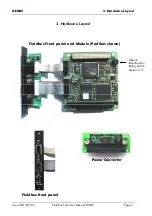
The site is now ready to receive a Fieldbus module.
(f)
Check that the connector pins on the underside of the Fieldbus module are correctly
aligned. Orientate the module so that the matching connectors are in line. Gently
push the connector halves together until the module sits flat on the mounting
pillars.
(g)
Insert the front panel mounted Fieldbus and diagnostic ribbon cables to their
associated headers.
(h)
Secure the Fieldbus module in position using 4 more mounting pillars.
(i)
If all required Fieldbus modules are now fitted proceed at instruction (j), otherwise
continue at instruction (e).
(j)
The site is now ready to receive the power converter module.