


GEM80
6. Maintenance and Fault Finding
Issue 002 (07/05)
Fieldbus Technical Manual T2035
Page 15
6.2
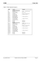
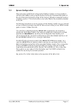
Version Buffer
The version buffer is optional; it is disabled by clearing Pn+10 for module 1 or Pn+26
for module 2. When configured, information about the associated module’s hardware
and software is copied to the buffer. The copy occurs once when the controller is
powered-up and again on recompilation of the controller. If insufficient entries are
allocated by the user the report will truncate.
Note. The information presented will be required when contacting the ALSTOM
customer support department.
Table (BYTE)
Offset
Content
Format
Example
Interpretation
0
@0501
2
Manufacture
Date
BCD
@0320
01/05/2003
4
@7910
6
Device
Type
BCD
@9040
10794090
8
@0000
10
Serial
Number
BCD
@2200
00000022
12
Memory size
BYTE
@08
8Kbytes
13
Type
BYTE
@03
Type 3
14
Model
ASCII
@31
Model ‘1’
15
@43
16
@49
17
Identification
ASCII
@46
‘CIF’
18
@4250
20
@432D
22
@404F
24
@4942
26
@3143
28
@3430
30
@2D50
32
Firmware
Name
ASCII
@4250
‘PB-COMBIC104P-PB’
34
@3056
36
@2E31
38
@3730
40
@2030
42
@3931
44
@312E
46
@2E30
48
Firmware
Version
ASCII
@3230
‘V01.070’ ’19.10.02’
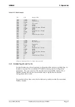
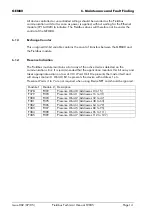
6.3
Fixed V-Table
The GEM80-500 controller has five V-Table entries (V67 to V71 inclusive) reserved for
plug-in module identifiers. The Fieldbus modules will also present their identifiers in
these table entries. The values presented are the lower half of the device type as read
from the Fieldbus module. These values follow on from the modules fitted directly to the
base board. These table entries are reported in the order that they are found by the
driver.