


GEM80
4. Installation
Issue 002 (07/05)
Fieldbus Technical Manual T2035
Page 6
(k)
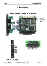
Check that the connector pins on the underside of the power converter module are
correctly aligned. Orientate the module so that the matching connectors are in line
and the mounting holes correspond with the two mounting pillars nearest to the
front of the controller. Gently push the connector halves together until the module
sits flat on the mounting pillars.
(l)
Secure the power converter module in position with 2 of the screws and washers
removed at instruction (c). The unused screws and washers may be stored in the
other two mounting pillars.
(m)
Remove a blanking panel from the front of the controller, to make space for each
of the Fieldbus module front panels. The blanking panels are secured with two M3
Pozi-pan screws, remove and retain the screws.
(n)
Secure the Fieldbus front panel(s) in position using the screws removed at
(o)
Replace the upper right-hand side cover and power supply assembly. Secure in
position using the screws removed at instruction (a).
WARNING
Insertion or removal of modules with the equipment
energised will cause malfunction of the equipment.
4.3
Module Identification
A rotary switch located on the fieldbus module PCB achieves module identification. A
maximum of two fieldbus modules can be installed into a GEM80-500, each identified
in the system by reserved rotary switch position 2 or 3.
The GEM80-500 Fieldbus driver will find the module with the lowest switch position
and use the configuration parameters from Pn to configure this module, this is referred
to as Module #1. The next module if fitted will use parameters from Pn+16, this
referred to as Module #2 (see section 5.2).
If a single Fieldbus module is fitted, the rotary switch must be set to position 2 (Module
#1). If two modules are fitted, one rotary switch must be set to positions 2 (Module
#1) and the other to position 3 (Module #2).
If a module is removed, ensure that the remaining module’s rotary switch is set to
position 2 and that the configuration data starting at Pn are suitable for the application.
N.B. If two modules are fitted, setting the rotary switch to the same position will cause
malfunction of both modules. Selecting any position other than 2 or 3 will cause
malfunction of the host processor.