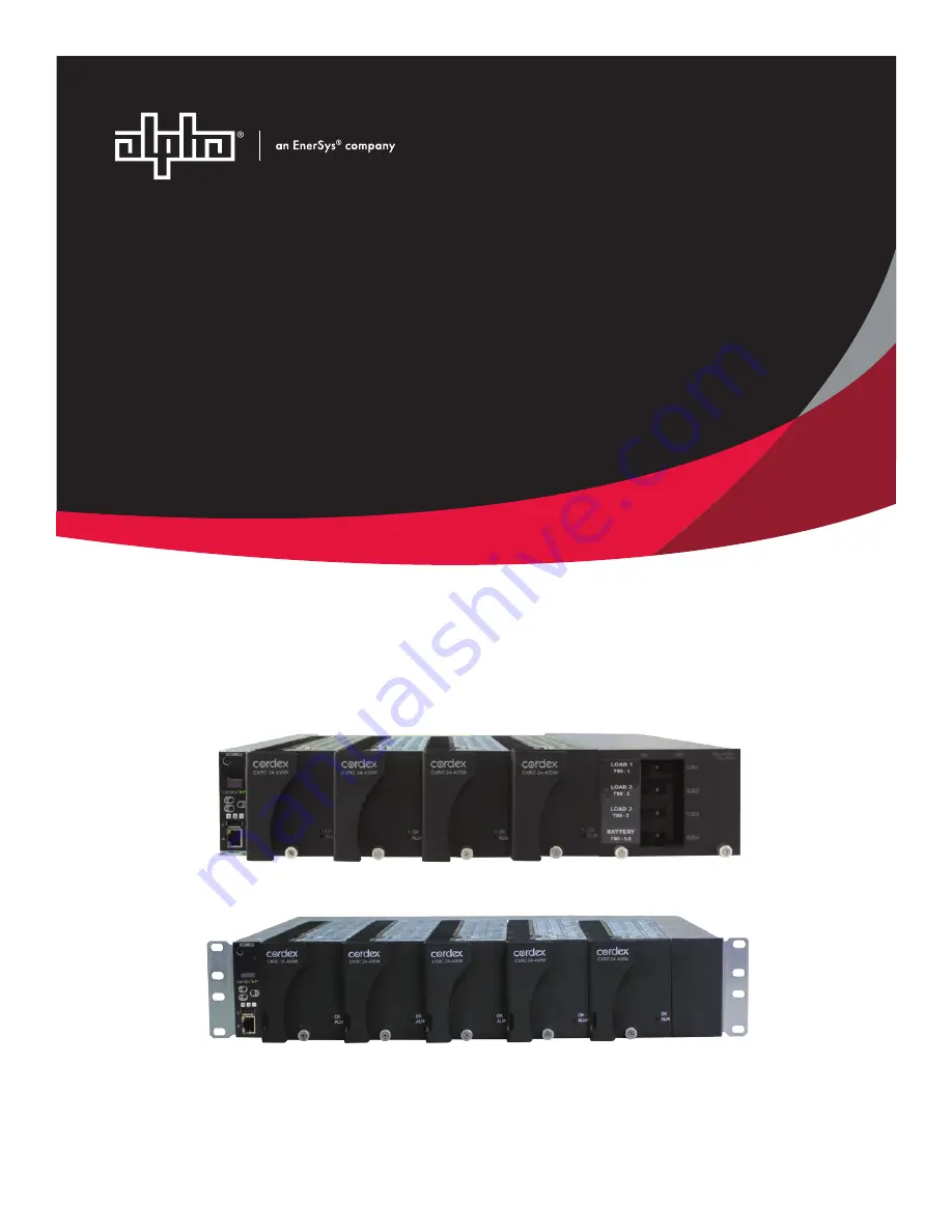
Cordex
®
24-400W
Rectifier Shelf System
Technical Guide: 9400021-J0Effective: 07/2020
Страница 1: ...Cordex 24 400W Rectifier Shelf System Technical Guide 9400021 J0 Effective 07 2020 ...
Страница 2: ......
Страница 3: ...mark of Alpha Technologies No part of this documentation shall be reproduced stored in a retrieval system translated transcribed or transmitted in any form or by any means manual electric electronic electromechanical chemical optical or other wise without prior explicit written permission from Alpha Technologies This document the software it describes and the information and know how they contain ...
Страница 4: ......
Страница 5: ... Removal 22 5 4 Removing a CXRC Rectifier 22 5 5 Removing the CXCi HP and CXCi Controller 22 6 Wiring and Connections 24 6 1 Safety Precautions 24 6 2 Tools Required 24 6 3 Power System Chassis Ground and DC Ground 24 6 4 AC Feeder Protection Sizing 24 6 5 AC Input 25 6 6 Calculating Output Wire Size Requirements 25 6 7 DC Output 26 6 8 CAN Ports 27 6 9 Network Connection and Remote Communications...
Страница 6: ...onnect 34 8 4 Controller Reset CXCi 34 8 5 Controller Reset CXCi HP 35 9 Maintenance 36 9 1 Replacing a CXCi Controller 36 9 2 Replacing a CXCi HP Controller 38 10 Warranty and Service Information 39 11 Certification 40 12 Glossary 41 13 Specifications 43 13 1 2RU 24 400W 19 4 Module System 43 13 2 2RU 24 400W 19 5 Module System 44 13 3 Cordex 24 400W Switched Mode Rectifier 45 13 4 CXCi HP Contro...
Страница 7: ... 11 Figure 4 CXCi HP Controller 14 Figure 5 In Shelf Controller Dashboard Screens 15 Figure 6 In Shelf Controller Menu 15 Figure 7 In Shelf Controller Buttons 16 Figure 8 Cordex CXCi model system controller front panel 17 Figure 9 Packing Materials and Environmental Codes 20 Figure 10 Digital Input Connection Method 29 Figure 11 Relay Connections 30 Figure 12 Removing the CXCi HP 38 Page 4 9400021...
Страница 8: ...efinitions for Digital Inputs 30 Table 5 Output Voltage Modes 32 Table 6 Output Current Power Modes 32 Table 7 Factory Ranges and Defaults 33 Table 8 Sample Maintenance Log 36 Table 9 Specifications 24 400W 19 4 Module System 43 Table 10 Specifications 24 400W 19 5 Module System 44 Table 11 Specifications Cordex 24 400W Switched Mode Rectifier 45 Table 12 Specifications CXCi HP Controller 48 Table...
Страница 9: ...s indicate safety information intended to PREVENT DAMAGE to material or equipment Warning Warnings present safety information to PREVENT INJURY OR DEATH to personnel Note HOT The use of Hot presents safety information to PREVENT BURNS to the technician or user General Warning and Cautions Warning You must read and understand the following warnings before installing the system and its components Fa...
Страница 10: ...e live Turn off all circuit breakers and double check with a voltmeter before performing installation or maintenance Place a warning label on the utility panel to warn emergency personnel that a reserve battery source is present which will power the loads in a power outage condition or if the AC disconnect breaker is turned off At high ambient temperature conditions the internal temperature can be...
Страница 11: ...n to cause cancer and birth defects or other reproductive harm Battery post terminals and related accessories contain lead and lead compounds Wash your hands after handling batteries Warning Follow battery manufacturer s safety recommendations when working around battery systems Do not smoke or introduce an open flame when batteries especially vented batteries are charging When charging batteries ...
Страница 12: ...hot swappable meaning they can be inserted or removed from the shelf without cutting power to or from the system or the load Additional power modules can be included with the system at the time of ordering or added after the shelf has been installed The shelf rectifier system is designed to operate with the Alpha CXCi series of controllers includes CXCi and CXCi HP which is built into the rectifie...
Страница 13: ...Cordex 24 400W 19 Integrated Shelf Installation and Operations Guide 2 Introduction Figure 1 Four Module System 030 763 20 XXX Figure 2 Five Module System 030 773 20 XXX Page 10 9400021 J0 Rev B ...
Страница 14: ... semiconductors and thus improves reliability Rectifier Front Panel Figure 3 Rectifier Front Panel LEDs The front panel LEDs provide rectifier status summary and help to locate a specific module with the controller OK The top LED green is on when AC is within valid range and the rectifier is delivering power to the load The LED will flash 2Hz when AC is outside the nominal range AC voltage is inva...
Страница 15: ...ctivated This circuit momentarily ramps up the output voltage to determine if the module will source current If no increase in current is detected the Module Fail alarm is activated The module will test once every 60 seconds for the condition until current is detected Output voltage ramping will cease upon detection of current 1 A minimum 2 5 load is required to avoid the Ramp Test Fail alarm this...
Страница 16: ...o stagger start a series of modules to prevent excessive loading of generators upon start up The built in timer delays the start up of the module depending on the value selected up to 120 seconds on CXCi and 250 seconds on CXCi HP via the controller A minimum one second delay is preset to allow charging of the input capacitors Current Limit Short Circuit Protection The current limit function deter...
Страница 17: ...view of the CXCi HP The CXC HP in shelf controllers have a small organic LED OLED display This display shows 30 characters total five lines high six characters wide and the controller has three navigation buttons and one reset button The in shelf display has three main operating modes dashboard menu and screen saver After 20 minutes with no activity the in shelf controller goes into screen saver m...
Страница 18: ... much like the LCD screens on the CXC HP When you enter a menu the top item is highlighted To go to another menu scroll through using the Forward and Back buttons To execute a highlighted menu item press the Select button To exit a menu and return to the main OLED dashboard scroll to the Back command and then press the Select button The figure below shows an example of the menu screen The followin...
Страница 19: ...m a file on a USB device Info Display controller information including serial number part number software and hard ware version Rotate Rotate the in shelf controller display information by 90 degrees Back Exit the menu and return to the OLED dashboard In Shelf Controller Buttons The following figure shows how the buttons are interpreted Figure 7 In Shelf Controller Buttons M e n u A L C O R e s e ...
Страница 20: ...t corresponds to the alarm status Only one LED is illuminated at a time during alarm conditions Green OK no alarms present Yellow Minor alarm is present no major alarms Red Major alarm is present Progress and Status Indication The LEDs are also used in the following situations Base unit validation All three LEDs on simultaneously File transfer Red LED illuminates when recovering from invalid firmw...
Страница 21: ...nd V2 for load voltage V2 is wired internally to the rectifier shelf to provide a reference for rectifier float voltage low voltage disconnect LVD system high voltage alarm and system low voltage alarm Wire V1 to battery to monitor battery voltage or change battery setting from V1 to V2 in Signals Configure Signals Current Inputs The controller software is pre configured to monitor I1 for load cur...
Страница 22: ...controller via a CAN bus A step by step connection wizard provided to establish remote communications with your controller is available via the Alpha website http www alpha ca downloads Controller Connections Located on the rear of the shelf are terminal block connections for the system control I O such as digital signals analog inputs and alarm relay outputs USB Port CXCi HP Only A USB 2 0 port i...
Страница 23: ...for our products Rectifiers UPSs and batteries are shipped on individual pallets and are packaged according to the manufacturer s guidelines Almost all of Alpha s packaging material is from sustainable resources and or is recyclable See the following table for the material and its environmental codes Figure 9 Packing Materials and Environmental Codes Cardboard Polyethylene Terephthalate Low Densit...
Страница 24: ...allations e g CSA UL CEC NEC OSHA and local fire codes 5 2 Shelf Preparation Mounting Warning This system is designed to be installed in a restricted access location that is inaccessible to the general public Note The shelf is designed for mounting in a clean and dry environment Allow at least 1 75 44mm 1 RU of free space above and below the unit for unrestricted cooling airflow 3 5 89mm 2RU is re...
Страница 25: ...if it does not seat properly All modules are keyed to ensure that the correct module polarity voltage type is used 5 4 Removing a CXRC Rectifier 1 To remove a module loosen the screw on the bottom of the faceplate Thumb Screw 2 Grasp the handle and pull out sliding the module away from the rear connector and out of the shelf 3 Place the new rectifier module on the shelf bottom and slide the module...
Страница 26: ...ng image to remove the controller Pull here to remove the controller from the shelf CAUTION When removing the controller in a live system that has an LVD ensure that the LVD override jumper is set to correct position to avoid possible service disruption Refer to the wiring and connections section of the manual and the connection drawings 9400021 J0 Rev B Page 23 ...
Страница 27: ...e wire Socket and ratchet set Imperial measure Anti static wrist strap Computer laptop with web browser Standard network cable for access using the Ethernet port 6 3 Power System Chassis Ground and DC Ground Warning For safety reasons ensure the system is properly bonded to the building s ground Both the shelf chassis ground via power system chassis ground and common return DC ground shall be conn...
Страница 28: ...ord proceed to the next section 2 Refer to the 08 customer connections drawings rear view back cover removed 3 Remove the metal cover from the rear of the shelf to expose the wire way for the input terminal blocks 4 Attach the conduit retainers to the wire way hole s and route the AC cables through 5 Secure the wires to the AC input and chassis ground terminals as required Tighten the cable connec...
Страница 29: ...s must be UL approved 1015 for Canadian users TEW type for European users must be EN or IEC approved wire Circuit Breaker Distribution Four Module shelf equipped with four AM style bullet type breakers factory configurable as four load breakers or two load breakers plus two battery breakers or three load breakers plus one battery breaker Five Module shelf bulk output only Note Battery breakers sho...
Страница 30: ...wing sections Ethernet Port for Network Connection The Ethernet port is designed for controller connection to a user supplied network TCP IP secured by user via a front panel RJ 45 jack Connect to the controller using a standard network cable Pinouts are shown in the connection drawings Ethernet Port for Local Connection Local access e g laptop computer is also possible from the Ethernet port conn...
Страница 31: ...located at the rear of this manual Custom configurations may be detailed within the Alpha power system documentation package Bundle the signal cables together and route them through the entry holes of the shelf Analog Inputs CAUTION Ensure the correct polarity is used for all input cable terminations The analog input channels are used to monitor various types of electrical signals The Voltage Inpu...
Страница 32: ...ired Connection Method Typical Alpha systems use the reset with Hot and trigger with Ground connection The digital input is wired in such a way that the Hot is wired directly into one of the input terminals positive input for 12V and 24V systems negative input for 48V systems The other input terminal is wired to the Ground common of the system through a relay dry contact usually located on the equ...
Страница 33: ...d not provide the redundant LVD control as with the assigned output pins described below LVD Control Load Disconnect or Battery Disconnect The disconnect option is controlled by and connected internally to relay K1 when applicable LVD Inhibit Should it be necessary to remove a CXCI series controller the customer connection board on the rear of the shelf provides shorting pins JP2 to inhibit or ove...
Страница 34: ...of time before transitioning to the next state The controller continues to monitor its inputs After the Start Delay state the rectifier transitions to the Soft Start state Note Soft start or current walk in gradually increases the voltage and current output of the rectifier upon startup This is done to reduce the instantaneous load on the AC source Soft Start When the Soft Start state is entered t...
Страница 35: ... Volt age Modes Active when Float Output voltage is set to the float voltage setting Equalize Output voltage is set to the equalize voltage setting Battery Test Output voltage is set to the battery test voltage setting Safe Output voltage is set to the safe mode voltage setting Manual Test Output voltage can be manually adjusted outside of the standard adjustment ranges Output Current Power Modes ...
Страница 36: ...75 29 30V 27 00V Equalize EQ Voltage 24 90 29 30V 27 50V Battery Test BT Voltage 22 00 26 00V 23 00V Over Voltage Protection OVP See note below 30 30V 28 50V Current Limit CL 23 100 100 Power Limit PL 0 100 100 Module Start Delay 0 250s 1s System Start Delay 0 600s 0s Low Voltage Alarm LVA 21 00 26 00V 22 00V High Voltage Alarm HVA 26 00 30 30V 27 75V Equalization EQ Timeout 1 2399h 30h Battery Te...
Страница 37: ...ting for low AC voltage alarming is 180Vac For nominal 120Vac operation it is recommended to reset this value to 100Vac Using the controller test the functionality of various module alarms and controls In addition perform a load test with the system using a resistive load box as needed 8 4 Controller Reset CXCi Soft Reset CAUTION Before removing a CXCi from a live system or performing controller m...
Страница 38: ... 8 5 Controller Reset CXCi HP Soft Reset CAUTION Ensure that a backup has been performed before starting this process Use the Backup feature accessed through the LCD at Shortcuts Backup Note When the controller is being reset the DC output voltage is maintained Temperature compensation user inputs and relay controls are not available until the controller has finished restarting 1 From the main das...
Страница 39: ...circuit cards Table 8 Sample Maintenance Log Procedure Date Completed Clean ventilation openings Inspect all system connections re torque as necessary Verify alarm control settings Verify alarm relay operation 9 1 Replacing a CXCi Controller This procedure is for replacing a CXCi controller Write down the controller communication information dynamic or static IP IP address and gateway 1 Connect a ...
Страница 40: ...ain LVD operation c If the LVD is controlled on NO contacts then JP2 pins 2 and 3 must be shorted together 4 Gently pull the controller from the slot 5 Place the new CXCi controller on the shelf bottom and slide into the rear connector at the back of the slot 6 Log on to the controller and go to Logs and Files Manage Configuration File Upload Site Configuration and select the saved cfg file After ...
Страница 41: ...controller from the shelf 1 Login to the web user interface 2 From the main dashboard go to Controller Advanced Functions Configuration File 3 Click on the Export Controller Clone button to save the configuration file Save the configuration file in a location easily accessed as it will be uploaded into the new controller 4 Gently pull the controller from the slot 5 Place the new controller on the ...
Страница 42: ...ages based upon equipment failure during or after the warranty period No other obligations are expressed or implied Warranty also does not cover damage or equipment failure due to cause s external to the unit including but not limited to environmental conditions water damage power surges or any other external influence The customer is responsible for all shipping and handling charges Where product...
Страница 43: ...Underwriters Laboratories may grant a license for the use of this mark which indicates compliance with both Canadian and US requirements 3 NRTL s Capabilities NRTLs are third party organizations recognized by OSHA US Department of Labor under the NRTL program The testing and certifications are based on product safety standards developed by US based standards developing organizations and are often ...
Страница 44: ...troller High Performance CXD Cordex DC DC Converter CXR Cordex Rectifier DC Direct current DCCT Direct Current Current Transducer DHCP Dynamic Host Configuration Protocol DOD Depth of discharge FCC Federal Communications Commission GUI Graphical User Interface Hint A hint is information about the state of the system or possible configuration problems ICMP Internet control message protocol IEC Inte...
Страница 45: ...tial and environmental guidelines for telecom OLED Organic LED in shelf controller display RFC Request For Comments a formal document or standard from the Internet Engineering Task Force IETF SCI Serial Communication Interface SELV Safety Extra Low Voltage SMTP Simple Mail Transfer Protocol SNMP Simple Network Management Protocol SNTP Simple Network Time Protocol SOC State of Charge TCP IP Transmi...
Страница 46: ...2 12 to 10 AWG Chassis ground M4 studs Communications CAN bus out RJ 12 offset DC Output Terminal blocks 6 AWG 16mm 2 maximum Signal wiring Terminal blocks 26 to 18 AWG 0 14 to 0 75mm 2 Compliance EN 60950 Rectifier output shall be rated SELV suitable for connections to TNV 1 circuits UL UL 60950 1 2014 CSA CAN CSA C22 2 No 60950 1 07 A1 2011 A2 2014 CE IEC EN EN 60950 1 2006 A11 2009 A1 2010 A12 ...
Страница 47: ...Input Dual feed terminal blocks 4 to 6mm 2 12 to 10 AWG Chassis ground M4 studs Communications CAN bus out RJ 12 offset DC Output 1 4 20 x 5 8 inch studs Signal wiring Terminal blocks 26 to 18 AWG 0 14 to 0 75mm 2 Compliance EN 60950 Rectifier output shall be rated SELV suitable for connections to TNV 1 circuits UL UL 60950 1 2014 CSA CAN CSA C22 2 No 60950 1 07 A1 2011 A2 2014 CE IEC EN EN 60950 ...
Страница 48: ...RMS to 10kHz 100mV wide band p p to 100MHz In accordance with FCC requirements we provide the following statement as specified in the FCC guidelines for conformance to Part 15 Class B Note This equipment has been tested and found to comply with the limits for a Class B digital device pursuant to part 15 of the FCC Rules These limits are designed to provide reasonable protection against harmful int...
Страница 49: ...y 87 at 208 240Vac and 50 100 load 92 2 peak Inrush current full load steady state current of the rectifier within rated limits Start up Ready Time 5 seconds excluding soft start to complete inrush limit routine and ac measure ment for OK signal Start up Delay Programmable up to 120 seconds to enable stagger start of multiple rectifiers and to minimize the effect on a supply source Soft Start User...
Страница 50: ...ectromagnetic Immunity EN 61000 4 4 Electrical Fast Transient Burst Immunity EN 61000 4 5 Power Line Surge Immunity EN 61000 4 6 Conducted Electromagnetic Immunity EN 61000 4 8 Power Frequency Magnetic Field EN 61000 4 11 Voltage Dips Short Interruptions and Variations ETS 300 019 1 1 Environmental Conditions Storage ETS 300 019 1 2 Environmental Conditions Transportation ETS 300 132 2 Power Suppl...
Страница 51: ... In accordance with FCC requirements we provide the following statement as specified in the FCC guidelines for conformance to Part 15 Class B Note This equipment has been tested and found to comply with the limits for a Class B digital device pursuant to part 15 of the FCC Rules These limits are designed to provide reasonable protection against harmful interference when the equipment is operated i...
Страница 52: ...larm and popup message tones 70dbl Dimensions 44mm H x 88mm W x 318mm D 1 73 H x 3 5 W x 12 5 D Weight 0 62kg 1 36lb Mounting Modular on Cordex series shelves Relay Outputs Four 4 Form C 60Vdc 1A maximum Digital Inputs Two 2 60Vdc Analog Inputs Two DC voltage 0 to 60Vdc One DC current compatible with 25mV to 200mV shunts Two temperature 0 to 5Vdc with power source Communication Ports Ethernet RJ 4...
Страница 53: ...Dips and Interruptions In accordance with FCC requirements we provide the following statement as specified in the FCC guidelines for conformance to Part 15 Class B Warning The CXCi has been tested and found to comply with the limits for a Class B digital device pursuant to part 15 of the FCC Rules These limits are designed to provide reasonable protection against harmful interference in a resident...
Страница 54: ...000m 1640 to 13124ft Hardware Specifications CPU Coldfire Display 4 digit LCD Front Panel Con trols Display pushbutton toggle switch for voltage V or current A Reset switch soft reset button hold for 3 seconds to reset IP LEDs System OK Green Power System Minor Alarm Yellow Power System Major Alarm Controller Fail Red Audio Built in speaker for alarm and popup message tones Dimensions 88mm H x 26m...
Страница 55: ...XCi Controller continued Specifications Basic Unit CXCi CAUTION TO REDUCE RISK OF FIRE USE ONLY 26 AWG 0 14mm 2 OR LARGER WIRE The above information is valid at the time of publication Consult factory for up to date ordering information Specifications are subject to change without notice Page 52 9400021 J0 Rev B ...
Страница 56: ......
Страница 57: ......
Страница 58: ......
Страница 59: ...TLK DC INTLK J2 L1 L2 GND GND L2 L1 TB4 TB3 CANCOM CANL 5VCAN CANH FAN ENABLE J3 1 J3 2 J3 3 J3 4 J3 7 J3 8 J3 9 J3 10 J3 13 J3 14 J3 37 J3 38 J3 39 J3 40 J3 41 J3 42 J3 43 J3 44 J3 27 J3 28 J3 29 J3 30 J3 31 J3 32 J3 33 J3 34 J3 17 J3 18 J3 19 J3 20 J3 23 J3 24 J3 25 J3 26 J2 26 J2 25 J2 24 J2 23 J2 20 J2 19 J2 18 J2 17 J2 34 J2 33 J2 32 J2 31 J2 30 J2 29 J2 28 J2 27 J2 44 J2 43 J2 42 J2 41 J2 40...
Страница 60: ...5 0 5 1 1 2006 02 RP GS UPDATED TO REV C ASSY B SDW UPDATED CXCI CONTR C LS 2011 07 CF LS ADD LIST 98 BP00337 D LS 2015 10 WH LS ADD LIST 400 E DESCRIPTION LTR APPD DATE DWN REVISIONS CHKD OPTION 19 6 OFFSET 19 RACK MOUNT OPTIONS OPTION 98 99 OR 400 CXCI CONTROLLER 010 582 20 CXRC POWER MODULE OPTION 90 MODULE BLANK OPTION 80 83 OR 84 DISTRIBUTION OPTION 22 5 OFFSET OPTION 21 FLUSH MOUNT OPTION 40...
Страница 61: ...N 22 5 OFFSET OPTION 19 6 OFFSET OPTION 21 FLUSH MOUNT 19 0 482 0 0 2 6 1 5 38 2 0 51 3 2 82 3 5 88 18 3 465 19 RACK OPTION 0 5 0 127 12 1 307 0 6 0 152 0 7 18 OPTION 23 6 OFFSET OPTION 26 5 OFFSET OPTION 25 FLUSH MOUNT 23 0 583 22 3 566 0 0 2 6 1 5 38 2 0 51 3 2 82 3 5 88 23 RACK OPTION DO NOT SCALE DRAWING 2 4 5 3 1 B E C A D 5 4 3 2 1 E D C B A ...
Страница 62: ...W GS CORRECTED RJ45 DETAIL E 2006 09 SDW JK UPDATED CXCI SUPERVISORY F 2007 04 MP GS CHANGED AC I P FROM L2 TO L2 N G 2007 10 JK GS CORRECTED JP2 PINOUT SHT 4 H 2008 01 SDW JK UPDATED NOTES J 2011 07 CF LS ADD LIST 98 SHT 2 BP00337 K CX SUPERVISORY CORDEX 400W MODULES DISPLAY PUSHBUTTON TOGGLE SWITCH V A SYSTEM STATUS LEDS CXCI RESET SWITCH SOFT RESET PUSH ONCE I P RESET HOLD FOR 3 SEC 4 CB POSITI...
Страница 63: ...PERVISORY CORDEX 400W MODULES SYSTEM STATUS LEDS 4 CB POSITION DISTRIBUTION MODULE BLANK LCD HARD RESET PUSH ONCE DISP TOGGLE CXCI RESET RST ETHERNET RJ45 TX 1 TX 2 RX 3 NOT CONNECTED 4 NOT CONNECTED 5 RX 6 NOT CONNECTED 7 NOT CONNECTED 8 LIST 98 ONLY DO NOT SCALE DRAWING 2 4 5 3 1 B E C A D 5 4 3 2 1 E D C B A ...
Страница 64: ...CK COVER REMOVED CUSTOMER CONNECTION BOARD NOT SHOWN L2 N L1 L2 N L1 DC OUTPUT TERMINAL BLOCKS MAX WIRE GAUGE 6 AWG TB3 FEEDS MODULES 1 AND 2 TB4 FEEDS MODULES 3 AND 4 TB3 TB4 TB1 TB2 AC CABLE ENTRY 0 875 CAN COM 1 CAN H 2 NOT CONNECTED 3 CAN L 4 NOT CONNECTED 5 5 V CAN 6 CAN OUT RJ12 PIN OUT J6 JP1 J6 DO NOT SCALE DRAWING 2 4 5 3 1 B E C A D 5 4 3 2 1 E D C B A ...
Страница 65: ...4 TB1 TB2 I1 25 24 TB13 NC C NO K1 NC C NO K2 NC C NO K3 K4 NO C NC 1 12 11 10 9 8 7 6 5 4 3 2 BATT HOT T2 T1 V1 D2 D1 23 22 21 20 19 18 17 15 16 14 13 TB11 TB12 CUSTOMER CONNECTION BOARD DETAIL USED INTERNALLY 1 2 3 4 USED INTERNALLY FOR LVD CONTROL IF EQUIPPED REFER TO MANUAL FOR JUMPER SETTINGS JP2 DO NOT SCALE DRAWING 2 4 5 3 1 B E C A D 5 4 3 2 1 E D C B A ...
Страница 66: ...TERPRET DIM AND TOL PER ASME Y14 5M 1994 X X X X XX ANGULAR 1 1 0 5 0 25 OPTION 21 FLUSH MOUNT OPTION 19 6 OFFSET 19 RACK MOUNT OPTIONS OPTION 80 SHOWN OPTION 90 MODULE BLANK 010 582 20 CXRC POWER MODULE OPTION 99 OR OPTION 400 OPTION 25 FLUSH MOUNT OPTION 23 6 OFFSET 23 RACK MOUNT OPTIONS OPTION 80 SHOWN OPTION 90 MODULE BLANK 010 582 20 CXRC POWER MODULE OPTION 99 OR OPTION 400 REVISIONS LTR DES...
Страница 67: ...2 6 1 5 38 2 0 51 3 2 82 3 5 88 19 RACK MOUNT OPTIONS 0 0 7 18 6 0 152 12 1 307 OPTION 19 6 OFFSET OPTION 21 FLUSH MOUNT 23 0 583 22 3 566 0 0 2 6 1 5 38 2 0 51 3 2 82 3 5 88 23 RACK MOUNT OPTIONS 0 0 7 18 6 0 152 12 1 307 OPTION 25 FLUSH MOUNT OPTION 23 6 OFFSET DO NOT SCALE DRAWING 2 4 5 3 1 B E C A D 5 4 3 2 1 E D C B A ...
Страница 68: ... SYSTEM STATUS LEDS DB9 MODEM NETWORK RST OK MIN MAJ CXCI V A OPTION 99 CXCi ETHERNET RJ45 TX 1 TX 2 RX 3 NOT CONNECTED 4 NOT CONNECTED 5 RX 6 NOT CONNECTED 7 NOT CONNECTED 8 DCD 1 RX 2 TX 3 DTR 4 COM 5 DSR 6 RTS 7 CTS 8 RI 9 DB9 FOR ARGUS DC MODEM USE ONLY 8 1 9 1 OPTION 98 CXCi OPTION 400 CXCi HP STATUS DISPLAY RESET ETHERNET 10 100 USB 2 0 PORT MENU CONTROL MENU SELECT BUTTON C ALARM STATUS HAR...
Страница 69: ...ODULES 1 AND 2 TB4 FEEDS MODULES 3 4 AND 5 TB1 TB2 THIS OUTPUT IS LVD CONTROLLED IF EQUIPPED L2 N L1 L2 N L1 JUMPER SETTINGS FOR JP1 CAN UNTERMINATED CAN TERMINATED LIST 0 CAN OUT RJ12 PIN OUT J9 1 CAN COM 2 CAN H 3 NOT CONNECTED 4 CAN L 5 NOT CONNECTED 6 5 V CAN LIST 80 CAN IN RJ12 PIN OUT J10 1 CAN COM 2 CAN H 3 NOT CONNECTED 4 CAN L 5 NOT CONNECTED 6 5 V CAN J9 JP1 J10 DO NOT SCALE DRAWING 2 4 ...
Страница 70: ... NC 1 12 11 10 9 8 7 6 5 4 3 2 BATT HOT T2 T1 V1 D2 D1 23 22 21 20 19 18 17 15 16 14 13 TB11 TB12 TB4 TB3 REAR VIEW BACK COVERS REMOVED TB1 TB2 L2 N L1 L2 N L1 REFER TO MANUAL FOR JUMPER SETTINGS FOR JP2 CUSTOMER CONNECTION BOARD DETAIL USED INTERNALLY FOR LVD CONTROL IF EQUIPPED 1 2 3 4 JP2 DO NOT SCALE DRAWING 2 4 5 3 1 B E C A D 5 4 3 2 1 E D C B A ...
Страница 71: ......
Страница 72: ...800 667 8743 Outside North America 1 604 436 5547 Technical Support 1 888 462 7487 For more information visit our website at www alpha com 2020 Alpha Technologies Ltd All Rights Reserved Trademarks and logos are the property of Alpha Technologies Ltd and its affiliates unless otherwise noted Subject to revisions without prior notice E O E ...