Kacper.Szyku
ł
a
Zaprojektowany przez
Sprawdzony przez
Zatwierdzony przez
Data
Materia
ł
Skala
0,15 :
1
A3
Nazwa cz
ęś
ci
SlimAIR - przestrze
ń
serwisowa
Format
Masa
Data
Data
09.11.2020
Nie
dotyczy
min. A mm
min. B mm
WYMIAR
HRU-SlimAIR-250
HRU-SlimAIR-350 HRU-SlimAIR-500
A
400
400
500
B
250
300
300
Kacper.Szyku
ł
a
Zaprojektowany przez
Sprawdzony przez
Zatwierdzony przez
Data
Materia
ł
Skala
0,15 :
1
A3
Nazwa cz
ęś
ci
SlimAIR - przestrze
ń
serwisowa
Format
Masa
Data
Data
09.11.2020
Nie
dotyczy
min. A mm
min. B mm
WYMIAR
HRU-SlimAIR-250
HRU-SlimAIR-350
A
400
400
B
250
300
G
D
C
F
B
4x Ø
A
E
WYMIAR
HRU-SlimAIR-250
HRU-SlimAIR-350
A
160
200
B
242
300
C
685
735
D
223
226,5
E
200
208,5
F
107
143
G
102
100
ALNOR
®
systemy wentylacji
jest prawnie chronionym znakiem i technicznym patentem. Prawo do zmian zastrzeżone.
46
w
w
w
.al
nor
.c
om.
pl
Instrukcja obsługi
HRU-SlimAIR
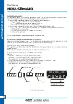
Fig. 27 - Maintenance space
4.5 Ducting installation
1. Usually the ducts are connected directly to the Ø160 fittings for HRU-SlimAIR-250 or Ø200 for
HRU-SlimAIR-350 and HRU-SlimAIR-500.
Although HRU-SlimAIR has very low Sound power level in some cases it is recommended to install additional
silencers (on supply and extract sides) to provide high level of acoustic comfort.
Description of connections:
SUPPLY – warm fresh air incoming to house
EXHAUST – cool stale air exhausted to outside
EXTRACT – warm stale air extracted from house
OUTDOOR – cool fresh air taken from outdoor
2. If you want use different duct connectors it is possible to unmount NSL male connectors and easily install
replacement fittings (for example elbow, offset bend, etc.). NSL connector are snap-on mounted, to
unmount them you need to pull them up using a some force.
Optional fittings connected to HRU must be in male-ended according to ALNOR’s dimension standards
(see our SPIRAL® catalogue with dimension tolerances). To provide the best tightness we suggest to use
ALNOR’s products with gasket. We are not responsible for tightness if fitting are purchased from other
companies.
Fig. 26 - Dimensions of nozzles for assembly taking into account the space for insulation
4.6 Maintenance space
The figure shows the minimum maintenance clearances needed to change filters, check the control circuit,
remove the heat exchanger. Filters can be changed from two positions, side and front. Caps are made for each
position so that the filter can be replaced without opening the front cover.
A
[mm]
B
[mm]
C
[mm]
D
[mm]
E
[mm]
F
[mm]
G
[mm]
SlimAIR-250
160
242
685
223
200
107
102
SlimAIR-350
200
300
735
226.5 208.5
143
100
SlimAIR-500
200
300
898
253.7 262.5 133.7 181.8
A
[mm]
B
[mm]
SlimAIR-250
400
250
SlimAIR-350
400
300
SlimAIR-500
500
300


