Allis-Chalmers fb-500 Скачать руководство пользователя страница 1

... 

·"'·

-

.. . 

·i 

""•  �  I  'I 

.. 

--

.. 

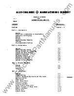
Installation, Care· and Operation 

of Circuit Breakers and Accessories 

TYPE 

11F" 

MOVABLE 

PORTION 

FB-500 

RUPTAIR  MAGNETIC 

POWER 

CIRCUIT 

BREAKER 

AND 

AUXILIARY 

�UIPMENT 

(SOLENOID  OPERATOR) 

OOOK 

BW.X:-6 639 

.. 

These 

instructions 

are 

not 

intended  to  cover  all 

__ 

details  or 

variations  t���- �ay  be  eneowttere�.  in 

connection  with 

the 

installation, 

maintenance 

of  this  equipment. 

Should  additional  inrormation 

be  desired 

contact 

the  Allis-Chalmers  Mfg.  Company. 

41115·(Hlll ER5  I F6. (0. 

Rn�TftN  wnDil� .  RO§TON 

• 

MA!!t.�L 

www 

. ElectricalPartManuals 

. com 

Содержание fb-500

Страница 1: ...OPERATOR OOOK BW X 6639 These instructions are not intended to cover all __details or variations t ay be eneowttere in connection with the installation opera t ion and maintenance of this equipment Should additional inrormation be desired contact the Allis Chalmers Mfg Company 41115 HlllER5 I F6 0 Rn TftN wnDil RO TON MA t L w w w E l e c t r i c a l P a r t M a n u a l s c o m ...

Страница 2: ...w w w E l e c t r i c a l P a r t M a n u a l s c o m ...

Страница 3: ... Contacts Mechanical Interlocks Positions in Cubicle Operate in Test Position P 3 Breaker Operation r General Closing Opening Part 4 Adjustments General Toggle Setting Operator Mee i_sm Main Latcl t__and PrQp Latch Auxiliary Switch Limit Swi tch _ I atch Check Switch Interlock Plunger Tripping Solenoid Arcing Contact Hinge Joint Contact Pressure of Hinge Joint Contact Alignment Contact Lead Contac...

Страница 4: ...w w w E l e c t r i c a l P a r t M a n u a l s c o m ...

Страница 5: ...alcer IAbzo1oation iJltCIDCt Qaid a Part 6 J plac Pan How to Ordel oo t lpt ra Me til 1qlacizta Panl Jl22u Juonen Ut lw lro Gat Blnlerltub lob ldal e ot Cbaolr l ld jutacte 01rcnd t Adjut Dct Talue SECTION NO J January 1962 ____ __ _ _____ ____ w w w E l e c t r i c a l P a r t M a n u a l s c o m ...

Страница 6: ...w w w E l e c t r i c a l P a r t M a n u a l s c o m ...

Страница 7: ...LUSTRATIONS FOR MAGNETIC BREAKER AND AUIILIARI 1UIPMENT I DESCRIPTION MAGNETIC BREAKER ARC cmm STUD AND SUPPORr OPERATOR AtJilLIAHI smcH OPERATOR LINKAGE DIAGRAM CWSING DEVICE TILTING BACK ABC CliU l 1 FIFTH WHEEL w w w E l e c t r i c a l P a r t M a n u a l s c o m ...

Страница 8: ...w w w E l e c t r i c a l P a r t M a n u a l s c o m ...

Страница 9: ... LEADS must be large enough to avoid VOLTAGE DROP Betore adjusting or repairing disconnect breaker from all sources of POWER and see that breaker is OPEN Unbolt ARC RUNNERS AND ARC CHUTE SUPPORr before tUthrg arc chutes Banier stacks require SPECIAL HANDLING to avoid dama e Avoid CWNING FLUIDS detrimental to insulation or paint Ieep GRAPHITE ort insulation under penalty o replacement 12 Do not dre...

Страница 10: ...w w w E l e c t r i c a l P a r t M a n u a l s c o m ...

Страница 11: ... D tile h1pl7 1 tiataotoi7 aemoe of which thq are e pable fhe fbl lcnd q JllllberiDS 171ta hu bee ad opte4 for reaq refercae ill t d 1 tn oticm l ook 1 2 liter to Seation ti of Part 1 4 220 B tf r to item 220 em 1Uuatrat10D lll l bcl f1ave 4 1 U I L Dp qp j p uiab T ud oizonS t breaker are o6 ted tllq re nb eotecl to a tr1 e1 of teeta ud inlpeotio Paak q 11 d OJW to UIVI mn1 p Jll O eoticm d vizl ...

Страница 12: ...w w w E l e c t r i c a l P a r t M a n u a l s c o m ...

Страница 13: ... POII and a IP dezo Uted where neoesaarr to prnlftt diatarticm ot trll l member ATO d ab ori hit ohet wbiah ooulA pl oe to maoh atrjin on part e of tht breaker uah u balhJ np intul tinl partt tittiq11 eto d ioh are not c etipld for tt uoturt l et r h 1 8 PJPHNSTU T A l ION mY CE Cl1rcndt breakers are oompl ete set up djultecl am teeted at the factor r HOWI l er s l noe there are possibilities tJ i...

Страница 14: ...w w w E l e c t r i c a l P a r t M a n u a l s c o m ...

Страница 15: ...ormance Close breaker with maintenance closing handle see photos Watch operation of operator linkages and contacts carefully Contacts should mate properly but need not make at same time on all phases Trip manually 1 43 Operate breaker several times electrical to check for smooth operation Tilt arc chutes to upright position see Section 6 3b and replace barriers see Section 6 3a Make certain the si...

Страница 16: ...w w w E l e c t r i c a l P a r t M a n u a l s c o m ...

Страница 17: ...r should be tried in each of the three positions in several cubicles to assure interchangeability 2 9 OPERATE IN TEST POSITION The breaker should be operated several times electricallY in its test position to see that all parts work correctly in final preparation for its operating position Make sure that secondary contacts of breaker are in eligmnent with secondary contacts in the cubicle Move the...

Страница 18: ...w w w E l e c t r i c a l P a r t M a n u a l s c o m ...

Страница 19: ...erclockwise about cent er B Mov811lent o oranlcarm 2 closes the breaker ani compresses the breaker opening springs 7 When links 4 and 5 reach their tinal position prop latch 10 drops behind center 011 to look the mechanism in the oloeed poeition as shown in Fig 14 llier closing the breaker armature 12 retlU DS to its normal position Manual closing is as described except that armature 12 is actuate...

Страница 20: ...w w w E l e c t r i c a l P a r t M a n u a l s c o m ...

Страница 21: ... l 32t 1 64 with the prop latch 4 97 and l 16 1 32 clearance to stop 4 59 4 3 OPERATOR MECHANISM MAIN LA TCH AND PROP LA TCH Fig 4 l he main operator latch 4 27 is in proper adjustment when the latch roll 4 15 A ages it at a point 3 161 0 1 16 from the bottom edge of the latch face 4 27 Changes in adjustment are made by positioning stop screW 4 65 The latch roll stop screw 4 75 should be positione...

Страница 22: ...w w w E l e c t r i c a l P a r t M a n u a l s c o m ...

Страница 23: ... plunger 1 18 sufficiently to release the breaker allowing it to be move i in the cubicle The interlock is in proper adjustment when the plunger 1 18 is positioned to l 3 4Z1 16 above the noor line and causes tripping or breaker contacts when it is raised to a level not more than 2 l 16 above the floor line The latch tripping rod associated with the foot lever ahould be clear of the trip latch 4 2...

Страница 24: ...w w w E l e c t r i c a l P a r t M a n u a l s c o m ...

Страница 25: ...aching link 1 47 to disconnect arms 3 18 and 3 19 check contact alignment Section 4 ll and contact lead Section 4 12 4 11 CONTACT ALIGNMENT Fig 3 The horizontal pairs of main contact fingers should make with the moving contacts simultaneously Note Contacts on different phases should not necessarily 11make simultaneously Remove pin 1 46 and detach link l 47 from the disconnect arms 3 18 and 3 19 of...

Страница 26: ...w w w E l e c t r i c a l P a r t M a n u a l s c o m ...

Страница 27: ...e maintained in proper adjustment Check and adjust as follows With breaker in closed position dimension See Fig 3 View A A Breaker Latched on the top pair or fingers should be 1 16 plus 3 64 0 Adjustment is made with the breaker in the open position by increasi or decreasing the effective length of link 1 47 by means or nuts 1 10 Each phase is adjusted individually After making the above adjustmen...

Страница 28: ...w w w E l e c t r i c a l P a r t M a n u a l s c o m ...

Страница 29: ... power ad that the breaker 11 ill the ope poaitioD ltetor U MiDtiDIDOe 11 tt ptede 5 1 coNTACtS IAapeot all aonta otl frequctly depenc lizl 011 aneritr of lenioei k41r pitte4 or bunled ccmtacta before they are dlu d to 1uch aa atct a1 to ca11 illproper operatiOil ot the breaker 5 3 IAUIIR STACKS The barrier atacka are fragile and should be handled caretully The barrier atack1 ahwld be inspected fo...

Страница 30: ...w w w E l e c t r i c a l P a r t M a n u a l s c o m ...

Страница 31: ... ioated wi h a liallt tila ot Aero J D bripl tt or equl Je U villa a val an req11i ot zoeqaat lubnoatia but ov lhoul d be taka o pr eatNaoe of dirt aD1 toreip ate rial d U iq mailltaa ue woJik K Uq nrtao ot u ia ID4 aroiD oontaota ebO ld aot be lurieated 2 6 Om u OI GUIDI We r to tile ttulatcl Sohedul e ot Glatekt IDII Acl tu D ta Ap u z 1 to a cU cen of pertiaat ut noticm book w uaa a pil e to ti...

Страница 32: ...w w w E l e c t r i c a l P a r t M a n u a l s c o m ...

Страница 33: ...ll moto l relaya mel coila or4ere4 Rated a perea of all motora relay aad ooil1 or ered 8 Rated voltaae of breaker t l ated amperes of bre lcer T bt breaker aerial awaber ia neceaaar7 to determine the correct i4tnti J ot a part1 without thia aerial IWII ber Allia ChalJIIIra Mta Co aumot bl ave of the correct identity of the cl11ired putt It U7 cloubt u iata I to the inatruction book reference or th...

Страница 34: ...w w w E l e c t r i c a l P a r t M a n u a l s c o m ...

Страница 35: ...38 501 2 6 2000 Amps 71 201 458 501 2 6 4 8 Coil Closing 71 208 440 1 1 4 17 Coil Trip 71 200 745 1 1 1 21 X Re1ay DC less coil 71 307 178 501 1 1 DC Coil 71 207 181 1 1 230V AC with coil W 643 201 1 1 115V AC with coil W 643 208 1 1 l 21 Y Relay and coil 125V DC W 541 306 1 1 250V DC W 541 307 1 1 48V DC W 541 309 1 1 230V AC W 643 2ll 1 1 115V AC W 643 212 1 1 1 25 Barrier Stack 71 302 897 502 1...

Страница 36: ...w w w E l e c t r i c a l P a r t M a n u a l s c o m ...

Страница 37: ...200 Amp 71 208 255 514 1 1 3 2000 Atnp 71 208 255 504 1 3 3 18 Disconnect Arm UI 1200 Amp 71 208 255 5il3 l 3 2000 Amp 71 208 255 503 1 3 3 25 Washer Silver 71 177 196 003 2 6 3 17 Washer Silver 71 177 196 005 2 6 3 2 3 Spring Washer 71 167 537 001 6 18 15 Belville Washer 71 140 901 001 4 12 i w w w E l e c t r i c a l P a r t M a n u a l s c o m ...

Страница 38: ...w w w E l e c t r i c a l P a r t M a n u a l s c o m ...

Страница 39: ...he breaker Replace the above parts in reverse order taking care that barrierJ are seated properly and that channels 1 9 are located inside of washers 1 S 6 3b TILTING ARC CHUTES Fig 1 Remove phase barriers See Section 6 3a Remove screws 1 1 1 37 and 1 39 on each phase With arc chute support in place tilt back the arc chutes After tilting arc chutes upright and before replacing phase barriers be su...

Страница 40: ...w w w E l e c t r i c a l P a r t M a n u a l s c o m ...

Страница 41: ...f the breaker Refer to Section 5 4 S Clean all parts of breaker An air blower is uset ul in removing dust tromgenerally inaccessible places 6 Cheek operatiDg mechaniam toggle adjustment per Section 4 2 7 Check trip latch 4 27 adjustment per Section 4 3 8 Check latch roll stop screw 4 75 adjustment per Section 4 3 9 Check prop latch 4 97 adjustment per Section 4 3 10 Check trip armature 4 17 tertra...

Страница 42: ...w w w E l e c t r i c a l P a r t M a n u a l s c o m ...

Страница 43: ...22 Inspect condition of control relaY contacts 23 Cheek contact alignment per Section 4 11 24 Check contact lead p er Section 4 12 25 Check contact stroke per Section 4 13 26 Check for barrier stack erosion per Section 5 3 27 Check condition of contacts 2S Reassemble breaker Be sure screws 1 1 1 37 d 1 39 are secured in each phase 29 theck breaker in cubicle Check general fit and line up Ch k o a ...

Страница 44: ...w w w E l e c t r i c a l P a r t M a n u a l s c o m ...

Страница 45: ...unger above noor line Max clearance plunger above floor line to trip breaker Clearance latch trip rod and trip latch Trip armature overtravel Pounds pull o disconnect blade Contaat alignment Dimension g View 11AA11 4 2 4 2 4 3 4 3 4 3 4 7 4 7 4 7 4 8 4 9 4 10 4 15 4 97 4 15 4 59 4 15 1 4 27 4 15 1 4 27 4 97 4 15 1 1a l 18 l 20 4 27 4 17 3 18 J 19 3 1Adjustment Values 1 32 1 64 l l6 t l 32 3 16 0 l...

Страница 46: ...w w w E l e c t r i c a l P a r t M a n u a l s c o m ...

Страница 47: ...ad Dimension 1 View 11AA Contact etroke Dimension View U Contact stroke1 Dimension Ret erence Section Ho1 4 ll 4 12 4 12 Illustration 1 Adjustment Nsh V ues 3 1 4 0 1 32 3 1 16 3 64 3 11 6 1 8 3 18 3 19 _ _ w w w E l e c t r i c a l P a r t M a n u a l s c o m ...

Страница 48: ...w w w E l e c t r i c a l P a r t M a n u a l s c o m ...

Страница 49: ... PHASE BARRIER ASSEMBLY F I G I 8 BARRIER 0 Jj A 6 CONNECTOR SCREW TRIP ROO 1 1 33 PtN FOOT LEVER INTERLOCK RELEASE 3i OPENtNG SPRING TYPICAL MAGNETIC B REAKER JUNE 13 1962 71 401 525 _ 1 w w w E l e c t r i c a l P a r t M a n u a l s c o m ...

Страница 50: ...w w w E l e c t r i c a l P a r t M a n u a l s c o m ...

Страница 51: ...L ARC RUNNER lr 1 I 1 I I I I I I I I I I I I I I I I I I I I I I I v I I I I l I I I I I I I I h I I I f l I I I I I I I I I v 0 o r r I I II I II I II I I I I I I I I p I I v r v F I G 2 T Y P I C A L A R C C H U T E JUNE 27 1962 7 1 4 0 1 5 3 2 1 nJ _ w w w E l e c t r i c a l P a r t M a n u a l s c o m ...

Страница 52: ...w w w E l e c t r i c a l P a r t M a n u a l s c o m ...

Страница 53: ... _ _ _ _ _ _ z J I I I I I f F I G 5 S ARCING CONTACT STATIONARY ARCING CONTACT MOVING PIN DISCONNECT ARM R HJ J VIEW B 6 T Y P I C A L STUD 8t S UP P O R T BREAKE R OPEN JUNE 13 1962 fl 401 524 S J f l rt J 1 J r u l L w Q r J t _ l __ J GiJ f J 1 J z 2 3 L 1 I J A r V J r J I _ 1 3 r Lt J iT 1 C1 J w w w w w E l e c t r i c a l P a r t M a n u a l s c o m ...

Страница 54: ...w w w E l e c t r i c a l P a r t M a n u a l s c o m ...

Страница 55: ... j i BACK PLATE WASHER LARGE t t LATCH CHECK SWITCH I FIG 4 TYPICAL OPERATOR ASSEMBL Y NOVEMBER 10 l9GI 71 302 979 J I A M c fill C fft A 0 z sC w w w E l e c t r i c a l P a r t M a n u a l s c o m ...

Страница 56: ...w w w E l e c t r i c a l P a r t M a n u a l s c o m ...

Страница 57: ...L L 1 f R O TOR CONTACT RETAit J ER ROTOR ASSEMBLY MOUNT ING BRACKET FIG I I TYPICAL AUXIL I ARY SW ITCH JULY 16 1 3 q 7 1 3CI 758 J A BEARING CRANK ARM I I MOUNTING BRACKE T I 1 c en fill 0 il m w w w E l e c t r i c a l P a r t M a n u a l s c o m ...

Страница 58: ...w w w E l e c t r i c a l P a r t M a n u a l s c o m ...

Страница 59: ...AKER OPENING SPRING TRIP FREE FIG 15 TO 8R AKER 2 TRIP eoJL 14 TRIP PIN IJ 9 TRIP FREE LATCH TYPICAL OPERATOR LINKAGE DIAGRAM i PrEMBEn 9 1953 71 40o 246 F CLOSED FIG 14 I BREAKER OPENING SPRING TO BREAKER J A A 1 BREAKER OPENING SPRING II W I a c c a 0 w w w E l e c t r i c a l P a r t M a n u a l s c o m ...

Страница 60: ...w w w E l e c t r i c a l P a r t M a n u a l s c o m ...

Страница 61: ...a se barrier a s s emblie s 3 off front o br eake r r Illust 2 0 51 3 0 Tilting arc chute s Position arc chute support unfa sten blowout coil connections and lower end of arc chute tilt t r c c hutes back on supports J I Ill t Ill Cl Ill A c ft 0 au arg w w w E l e c t r i c a l P a r t M a n u a l s c o m ...

Страница 62: ...w w w E l e c t r i c a l P a r t M a n u a l s c o m ...

Страница 63: ...ALLIS CHALMERS MAIUFACTUIIIG COMPAIY Manual Closing Device Fifth Wheel Illust 20512 7 lllust 2 05128 w w w E l e c t r i c a l P a r t M a n u a l s c o m ...

Страница 64: ...w w w E l e c t r i c a l P a r t M a n u a l s c o m ...

Отзывы: