Allied BCE5E Series Скачать руководство пользователя страница 17

507788-01

Issue 2007

Page 17 of 20

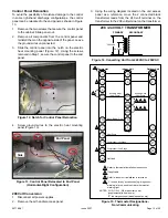
Check Electric Heat (If Used)

1.   Set thermostat to call for auxiliary heat (approximately 

5°F above ambient temperature). The indoor blower 

and auxiliary heat should come on together. Allow a 

minimum of 3 minutes for all sequencers to cycle on.

2.   Set the thermostat so that it does not call for heat. 

Allow up to 5 minutes for all sequencers to cycle off. 

Operation

Cooling (Cooling Only or Heat Pump)

When the thermostat calls for cooling, 24 volts is applied to 

the indoor blower motor relay. The normally open contacts 

close,  causing  the  indoor  blower  motor  to  operate; 

depending  on  the  indoor  blower  motor,  there  may  be  a 

delay. The circuit between 

R

 and 

Y

 is completed, closing 

the circuit to the contactor in the outdoor unit, starting the 

compressor and outdoor fan motor. 

On heat pumps, circuit 

R

 and 

O

 energizes the reversing 

valve,  switching  the  valve  to  the  cooling  position.  (The 

reversing valve remains energized as long as the 

thermostat selector switch is in the 

COOL 

position.)

At the completion of the cooling demand, the indoor blower 

and outdoor unit should cycle off. Air handler should cycle 

off 45 seconds after the outdoor unit shuts off.

Heating (Electric Heat Only)

When the thermostat calls for heat, the circuit between 

R


and 

W

 is completed, and the heat sequencer is energized. 

A time delay follows before the heating elements and the 

indoor  blower  motor  come  on.  Units  with  a  second  heat 

sequencer can be connected with the first sequencer to 

W


on the thermostat sub-base, or they may also be connected 

to a second stage on the sub-base.

Heating (Heat Pump)

When the thermostat calls for heating, 24 volts is applied to 

the indoor blower motor relay. The normally open contacts 

close,  causing  the  indoor  blower  motor  to  operate; 

depending  on  the  indoor  blower  motor,  there  may  be  a 

delay. The circuit between 

R

 and 

Y

 is completed, closing 

the circuit to the contactor in the outdoor unit, starting the 

compressor and outdoor fan motor. 

If the room temperature continues to decrease, the circuit 

between 

and 

W1

 is completed by the second-stage heat 

room thermostat. Circuit 

R-W1

 energizes a heat sequencer. 

The completed circuit will energize supplemental electric 

heat (if applicable). Units with a second heat sequencer 

can be connected with the first sequencer to 

W1 

on the 

thermostat. They may also be connected to a second 

heating stage 

W2 

on the thermostat sub-base.

Emergency Heat (Heating Heat Pump)

If  the  selector  switch  on  the  thermostat  is  set  to  the 

emergency heat position, the heat pump will be locked out 

of the heating circuit, and all heating will be electric heat (if 

applicable). A jumper should be placed between 

W2

 and 

E


on the thermostat sub-base so that the electric heat control 

will transfer to the first-stage heat on the thermostat. This 

will  allow  the  indoor  blower  to  cycle  on  and  off  with  the 

electric heat when the fan switch is in the AUTO position.

Professional Maintenance

Failure to follow instructions will cause damage to the 

unit.

This  unit  is  equipped  with  an  aluminum  Omniguard

TM


coil. Aluminum coils may be damaged by exposure to 

solutions with a pH below 5 or above 9. The aluminum 

coil  should  be  cleaned  using  potable  water  at  a 

moderate pressure (less than 50psi). If the coil cannot 

be cleaned using water alone, it is recommended to use 

a coil cleaner with a pH in the range of 5 to 9. The coil 

must be rinsed thoroughly after cleaning.

In coastal areas, the coil should be cleaned with potable 

water several times per year to avoid corrosive buildup 

(salt).

NOTICE

Homeowner Maintenance

Do not operate system without a filter. A filter is required 

to  protect  the  coil,  blower,  and  internal  parts  from 

excessive dirt and dust. The BCE5E units are shipped 

with  filters.  Remove  this  filter  if  the  return  air  register 

already has a filter.

 IMPORTANT

• 

Inspect air filters at least once a month and replace or 

clean as required. Dirty filters are the most common 

cause of inadequate heating or cooling performance.

• 

Replace filters with equivalent style filter.

• 

Cleanable  filters  can  be  cleaned  by  soaking  in  mild 

detergent and rinsing with cold water.

• 

 If water should start coming from the secondary drain 

line,  a  problem  exists  which  should  be  investigated 

and corrected. Contact a qualified service technician.

Содержание BCE5E Series

Страница 1: ...t Lines 9 Sealing the Unit 11 Electrical Connections 12 Blower Performance Data 15 Air Flow Cooling Blower Speed 16 Checkout Procedures 16 Operation 17 Professional Maintenance 17 Homeowner Maintenance 17 Cabinet Insulation 18 Improper installation adjustment alteration service or maintenance can cause property damage personal injury or loss of life Installation and service must be performed by a ...

Страница 2: ...NS 2 Horizontal 1 3 4 44 3 4 19 2 3 4 70 3 1 2 89 PIPING PLATE 4 3 4 121 4 3 8 111 2 3 8 60 CONDENSATE DRAINS 2 Upflow and Downflow SUCTION LINE CONDENSATE DRAIN PIPING PLATE 3 2 1 4 x 3 3 4 NOTE Unit is shipped configured for horizontal right hand air discharge Unit may be converted to horizontal left hand air discharge by repositioning horizontal drain pan Dimensions remain the same in all confi...

Страница 3: ...pplied in separate equipment before starting the installation In addition to conforming to manufacturer s installation instructions and local municipal building codes installation of air handler units with or without optional electric heat MUST conform with National Fire Protection Association NFPA standards Standard for Installation of Air Conditioning and Ventilation Systems NFPA No 90A and Stan...

Страница 4: ... replaced upon construction completion Installation Clearances Non Ducted Return Closet Installation The air handler can be installed in a closet with a false bottom to form a return air plenum It may also be installed with a return air plenum under the air handler Louvers or return air grilles are field supplied Local codes may limit application of systems without a ducted return to single story ...

Страница 5: ...t installed in right or left hand applications The coil may tip into the drain pan once it is clear of the cabinet Support the coil when removing it IMPORTANT NOTE When the unit is installed in horizontal applications a secondary drain pan is recommended Refer to local codes NOTE This unit may be installed in left hand or right hand air discharge horizontal applications Adequate support must be pr...

Страница 6: ...as the horizontal drain pan as illustrated in Detail A in Figure 5 NOTE Be very careful when reinstalling the screws into the coil end plate engaging holes Misaligned screws may damage the coil 9 From the upflow position flip cabinet 90º to the left and set into place Replace blower assembly Secure coil in place by bending down the tab on the cabinet support rail as illustrated NOTE Seal around th...

Страница 7: ...DARY DRAIN PLUG UNSCREW PLUGS AND CONNECT PROPERLY SIZED FIELD PROVIDED FITTINGS AND DRAIN LINES GREEN MAIN DRAIN PLUG Figure 7 Drain Line Connections 2 Install properly sized field provided connection fittings and connect primary drain line to the main drain pan connection NOTE When installing drain line connection fittings to the drain pan hand tighten the fitting and use a thread sealant Over t...

Страница 8: ... 2 CUT TO REQUIRED LENGTH SIDE VIEW Figure 8 Typical Main and Overflow Drain 7 Route the drain line to the outside or to an appropriate drain Drain lines must be installed so they do not block service access to the front of the air handler A 24 clearance is required for filter coil or blower removal and service access NOTE Check local codes before connecting the drain line to an existing drainage ...

Страница 9: ... provided by the filter manufacturer against the data given in the appropriate Product Specifications Additional information is provided in Service and Application Note ACC002 August 2000 IMPORTANT Installing Duct System Connect supply air duct to the flange on top of the air handler If an isolation connector is used it must be nonflammable Field Fabricated Return Air Duct Flange For Horizontal Ap...

Страница 10: ...ORE INSTALLING EITHER REMOVE OR PUSH PIPE WRAPPING BACK THROUGH HOLE IN PIPING PLATE BEFORE LINE SET CONNECTION AND BRAZING CONNECT PIPES NOTE REFRIGERANT LINE SETS SHOULD BE ROUTED TO ALLOW FILTER ACCESSIBILITY PLEASE READ IMPORTANT ISSUES CONCERNING BRAZING OPERATIONS IN THE BRAZING REFRIGERANT LINES SECTION BEFORE PROCEEDING CONNECT GAUGES AND START NITROGEN FLOW FLOW REGULATED NITROGEN AT 1 TO...

Страница 11: ... Recommended line length is 50 or less If more than 50 line set is required contact Technical Services NOTE Sealing the Unit Seal the unit so that warm air is not allowed into the cabinet Warm air introduces moisture which results in water blow off problems This is especially important when the unit is installed in an unconditioned area If installed in an unconditioned space sealant should be appl...

Страница 12: ...local building codes Refer to following wiring diagrams See unit nameplate for minimum circuit ampacity and maximum over current protection size Electrical wiring disconnect means and over current protection are to be supplied by the installer Refer to the air handler rating plate for maximum over current protection minimum circuit ampacity as well as operating voltage Select the proper supply cir...

Страница 13: ... 208 Volt Conversion 1 Disconnect all power supplies 2 Remove the air handler access panel 3 Using the wiring diagram located on the unit access panel as a reference move the 2 connected black transformer leads from the 240 volt terminal on the transformer to the 208 volt terminal on the transformer 208 240 VOLT TRANSFORMER PRIMARY SECONDARY 240 Volts 208 Volts Figure 14 Converting Unit from 240VA...

Страница 14: ...507788 01 Issue 2007 Page 14 of 20 4KW 5KW Figure 16 Typical Wiring Diagram BCE5E Air Handler with Electric Heat Constant Torque Motor ...

Страница 15: ...1060 4 Nominal 3 ton match with electric heat 1440 1400 1330 1280 1240 5 High static application 1540 1475 1430 1380 1300 42 1 Fan Only 990 915 860 810 725 2 Matched with 3 ton condensing unit 1190 1150 1100 1060 1020 3 Nominal 3 5 ton match without electric heat 1390 1350 1315 1280 1230 4 Nominal 3 5 ton match with electric heat 1665 1625 1585 1550 1510 5 High static application 1750 1710 1675 16...

Страница 16: ...ing for electric heat Table 5 Checkout Procedures NOTE Refer to outdoor unit installation instructions for system start up instructions and refrigerant charging instructions Pre Start Up Checks Is the air handler properly and securely installed If horizontally configured is the unit sloped up to 5 8 inch toward drain lines Will the unit be accessible for servicing Has an auxiliary pan been provide...

Страница 17: ...ween R and W1 is completed by the second stage heat room thermostat Circuit R W1 energizes a heat sequencer The completed circuit will energize supplemental electric heat if applicable Units with a second heat sequencer can be connected with the first sequencer to W1 on the thermostat They may also be connected to a second heating stage W2 on the thermostat sub base Emergency Heat Heating Heat Pum...

Страница 18: ...ads to sheet metal corrosion and subsequently component failure Repairing Damaged Insulation Areas of condensation on the cabinet surface are an indication that the insulation is in need of repair If the insulation in need of repair is otherwise in good condition the insulation should be cut in an X pattern peeled open glued with an appropriate all purpose glue and placed back against the cabinet ...

Страница 19: ...ing Mode Return Duct Temperature ___________ THERMOSTAT Adjusted and Programmed Return External Static ______ ______ Total External Static ______ ______ 6 Supply Duct Temperature ___________ Temperature Drop ___________ TEMPERATURE RISE Heating Mode Return Duct Temperature __________ Supply Duct Temperature __________ Temperature Rise __________ Operation Explained to Owner 9 Explained Operation o...

Страница 20: ...______ Total External Static ______ ______ 6 6 Supply Duct Temperature ___________ Temperature Drop ___________ TEMPERATURE RISE Heating Mode Return Duct Temperature __________ Supply Duct Temperature __________ Temperature Rise __________ Operation Explained to Owner 9 Electric Heat Amps 7 Explained Operation of System to Homeowner Technician s Name _______________________Date Start Up Performanc...

Отзывы: