507788-01
Issue 2007
Page 16 of 20
Air Flow - Cooling Blower Speed
The cooling blower speed is factory configured to provide
correct air flow for an outdoor unit that matches the cooling
capacity rating of the air handler (Tap 3).
If the outdoor unit is smaller than the maximum cooling
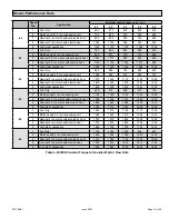
capacity rating for the air handler, the cooling blower speed
may need to be changed. Refer to blower performance
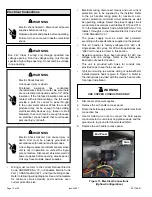
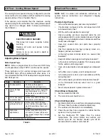
ELECTRIC SHOCK HAZARD!
Disconnect all power supplies before
servicing.
Replace all parts and panels before
operating.
Failure to do so can result in death or
electrical shock.
WARNING
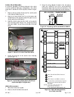
Adjusting Blower Speed
Motor Speed Taps
NOTE
-
Motor is programmed for a 45-second OFF delay
on all speed taps except TAP #1 (continuous fan speed).
These settings are for nominal tonnage match-ups with
the BCE5E
units. When matched with other sizes, it is
recommended that the CFM be adjusted to approximately
400 CFM per ton.
Tap
Operation
Remarks
1
Continuous fan
Continuous fan speed is
energized (24 volt input to G).
2
Lower tonnage
speed
Air flow set at 1/2 ton lower than
nominal capacity (e.g. if 3-ton
air handler is used with 2.5-ton
outdoor unit).
3
A/C or heat pump -
no electric heat
Air flow set at 400 SCFM per ton
at minimum static allowed.
4*
A/C or Heat pump
with electric heat
Air flow set at 400 SCFM per
ton at .5 static. Energized when
electric heat element has a call
for heat.
5
High static
applications
Air flow set at 400 cfm per ton
at .8 static. (Connect white wire
from blower relay to Tap 5 instead
of Tap 4)
* Tap 4 is minimum setting for electric heat
Table 5.
Checkout Procedures
NOTE:
Refer to outdoor unit installation instructions for
system start-up instructions and refrigerant charging
instructions.
Pre-Start-Up Checks
• Is the air handler properly and securely installed?
•
If horizontally configured, is the unit sloped up to 5/8
inch toward drain lines?
• Will the unit be accessible for servicing?
• Has an auxiliary pan been provided under the unit
with separate drain for units installed above a finished
ceiling or in any installation where condensate overflow
could cause damage?
• Have ALL unused drain pan ports been properly
plugged?
• Has the condensate line been properly sized, run,
trapped, pitched, and tested?
• Is the duct system correctly sized, run, sealed, and
insulated?
•
Have all cabinet openings and wiring been sealed?
• Is the indoor coil factory-installed TXV properly sized
for the outdoor unit being used?
• Have all unused parts and packaging been disposed
of?
•
Is the filter clean, in place, and of adequate size?
•
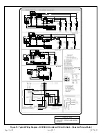
Is the wiring neat, correct, and in accordance with the
wiring diagram?
• Is the unit properly grounded and protected (fused)?
•
Is the thermostat correctly wired and in a good
location?
• Are all access panels in place and secure?
Check Blower Operation
1. Set thermostat to FAN ON.
2.
The indoor blower should turn on.
Check Unit Operation
1. Set thermostat to force a call for cooling (approximately
5ºF lower than the indoor ambient temperature).
2. The outdoor unit should turn on immediately.
3.
Check the air flow from a register to confirm that the
system is moving cooled air.
4.
Set the thermostat 5ºF higher than the indoor
temperature. The indoor blower and outdoor unit
should cycle off. Air handler should cycle off 45
seconds after the outdoor unit shuts off.

