Allied Telesis AT-FS909M Скачать руководство пользователя страница 1

613-001985 Rev A

AT-FS909M
AT-FS917M
AT-FS926M

Fast Ethernet Switches

Installation Guide 

Содержание AT-FS909M

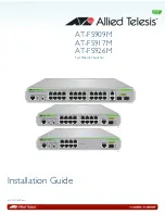
Страница 1: ...613 001985 Rev A AT FS909M AT FS917M AT FS926M Fast Ethernet Switches Installation Guide...

Страница 2: ...espective owners Allied Telesis Inc reserves the right to make changes in specifications and other information contained in this document without prior written notice The information provided herein i...

Страница 3: ...ot installed and used in accordance with this instruction manual may cause harmful interference to radio communications Operation of this equipment in a residential area is likely to cause harmful int...

Страница 4: ...ty Statements Important The indicates that a translation of the safety statement is available in a PDF document titled Translated Safety Statements posted on the Allied Telesis website at www alliedte...

Страница 5: ...n 31 Reviewing Safety Precautions 32 Selecting a Site for the Switch 35 Cable Specifications 36 Unpacking the Switch 37 Installing the Power Cord Retaining Clip 39 Installing the Switch on a Desktop o...

Страница 6: ...Contents 6...

Страница 7: ...aining Plates 39 Figure 10 Installing Retaining Plates on the Power Connector 40 Figure 11 Inserting the Retaining Clip into the Retaining Bracket 40 Figure 12 Attaching the Rack Mount Brackets to the...

Страница 8: ...List of Figures 8...

Страница 9: ...Table 6 SFP Slot LED Functional Descriptions 26 Table 7 Twisted Pair Cabling and Distances 36 Table 8 Chassis Dimensions 53 Table 9 Chassis Weight 53 Table 10 Environmental Specifications 53 Table 11...

Страница 10: ...List of Tables 10...

Страница 11: ...de contains the installation instructions for the AT FS909M AT FS917M and AT FS926M Fast Ethernet Switches This preface contains the following sections Symbol Conventions on page 12 Contacting Allied...

Страница 12: ...tions inform you that performing or omitting a specific action may result in equipment damage or loss of data Warning Warnings inform you that performing or omitting a specific action may result in bo...

Страница 13: ...ickets learn about Return Merchandise Authorizations RMAs and contact Allied Telesis technical experts USA and EMEA phone support Select the phone number that best fits your location and customer type...

Страница 14: ...14...

Страница 15: ...26M Layer 2 Fast Ethernet Switches and contains the following sections Features on page 16 Front and Back Panels on page 18 Management Software on page 20 Twisted Pair Ports on page 21 Combo Ports on...

Страница 16: ...half duplex operation RJ 45 connectors SFP Slots All three switches support both 100Base FX and 1000Base SX LX transceivers The switches support slots for SFPs as follows One SFP slot on the AT FS909M...

Страница 17: ...tions The AT FS900M Series switches can be installed in the following ways Rack mounted in a 19 inch equipment rack Mounted on a desk or tabletop If installing the switch in an equipment rack rack mou...

Страница 18: ...n SFP Console Port Status LEDs Mode Button Mode LEDs SFP LED with Port LEDs Slot 10 100 1000Base T Combo Port with Port LED 10 100 100Base T Twisted Pair Ports Reset Button SFP Console Port Status LED...

Страница 19: ...FS926M Switches Installation Guide 19 Figure 2 illustrates the back panels of the AT FS909M AT FS917M and AT FS926M switches Figure 2 AT FS909M AT FS917M and AT FS926M Back Panels AT FS926M AT FS909M...

Страница 20: ...ent In the unlikely event that the management software becomes corrupted or damaged on the switch you can download the software from the Allied Telesis corporate web site and reinstall it on the switc...

Страница 21: ...of 100 m 328 feet For 10 Mbps operation the ports require Category 3 or better 100 ohm shielded or unshielded twisted pair cabling For 100 Mbps operation the ports require Category 5 or Enhanced Categ...

Страница 22: ...pty or when an SFP module is installed but has not established a link to an end node The twisted pair port automatically changes to the redundant status mode when an SFP module establishes a link with...

Страница 23: ...T LED on page 24 The STATUS LEDs are located on the left side of the front panel of the switch See Figure 3 Figure 3 STATUS LEDs POWER LED The POWER LED reports the status of AC power Table 2 describe...

Страница 24: ...ion of the Mode button refer to Mode Button on page 28 The MODE LEDs are located on the left side of the front panel of the switch See Figure 4 Figure 4 MODE LEDs Table 4 on page 25 describes the MODE...

Страница 25: ...Green SPEED is the selected mode Ports display SPEED status Off SPEED is not the selected mode Ports display DUPLEX status DUPLEX Steady Green DUPLEX is the selected mode Ports display DUPLEX status O...

Страница 26: ...lished Steady Green The maximum operating speed of the port is 100 Mbps Duplex Off Half duplex link established or link not established Steady Green Full duplex link established Table 5 Port LED Funct...

Страница 27: ...sing the Reset button resets your switch The Reset button is located next to the STATUS LEDs See Figure 3 on page 23 This initiates a system reboot of the switch and reloads the current configuration...

Страница 28: ...r 1 Overview 28 Mode Button Use the Mode button to select whether the Port LEDs display the Link Activity or speed and duplex status The Mode button is located next to the MODE LEDs See Figure 4 on pa...

Страница 29: ...has an internal power supply with a single AC power supply socket on the back panel To power the switch on or off connect or disconnect the power cord provided with the switch A power cord is supplie...

Страница 30: ...Chapter 1 Overview 30...

Страница 31: ...h on page 35 Cable Specifications on page 36 Unpacking the Switch on page 37 Installing the Power Cord Retaining Clip on page 39 Installing the Switch on a Desktop or Table on page 41 Installing the S...

Страница 32: ...opened by a trained and qualified technician To avoid the possibility of electric shock disconnect electric power to the product before connecting or disconnecting the cables E1 Warning Do not work on...

Страница 33: ...ircuits might have on over current protection and supply wiring Appropriate consideration of equipment nameplate ratings should be used when addressing this concern E21 Warning Mounting of the equipme...

Страница 34: ...34 Warning Reliable earthing of rack mounted equipment should be maintained Particular attention should be given to supply connections other than direct connections to the branch circuits for example...

Страница 35: ...cure The power outlet for the switch should be located near the unit and should be easily accessible The site should provide for easy access to the ports on the front of the switch This will make it e...

Страница 36: ...sted pair cable when connecting any type of network device to a port on the switch Table 7 Twisted Pair Cabling and Distances Speed Type of Cable Maximum Operating Distance 10 Mbps Standard TIA EIA 56...

Страница 37: ...t use the original shipping material if you need to return the unit to Allied Telesis 2 Place the switch on a level secure surface 3 In addition to the switch verify that the shipping container includ...

Страница 38: ...rubber feet pre installed One regional AC power cord One or two SFP slot dust covers pre installed for desktop installation Two equipment rack brackets not included in AT FS909M or AT FS917M package F...

Страница 39: ...igure 8 Figure 8 Power Cord Retaining Clip For the AT FS926M also locate the power cord retaining plates in addition to the clip as shown in Figure 9 Figure 9 Power Cord Retaining Plates 2 For the AT...

Страница 40: ...e clip on the AC power connector on the back panel of the switch With the u of the clip facing down press the sides of the clip toward the center and insert the short ends into the holes in the retain...

Страница 41: ...rack see Installing the Switch in an Equipment Rack on page 42 To place the switch on a desktop or table perform the following procedure 1 Remove all equipment from the package and store the packagin...

Страница 42: ...inch equipment rack perform the following procedure 1 If the rubber feet are attached to the bottom of the switch remove them using a flat head screwdriver 2 Attach the two rack mount brackets to the...

Страница 43: ...AT FS909M AT FS917M and AT FS926M Switches Installation Guide 43 4 Go to Installing SFP Transceivers on page 44 or skip to Cabling the Switch on page 47 if not installing SFP transceivers...

Страница 44: ...ansceiver before connecting the fiber optic cables to it 1 Remove the transceiver from its shipping container and store the packaging material in a safe location Warning An SFP transceiver can be dama...

Страница 45: ...ceiver and prevents it from being dislodged from the slot Figure 16 Positioning the SFP Handle in the Upright Position 6 Repeat Step 2 through Step 5 to install additional SFP transceivers Note SFP tr...

Страница 46: ...Chapter 2 Installation 46 For information on the cable specifications of the SFP consult the documentation shipped with the SFP 7 Go to Cabling the Switch on page 47...

Страница 47: ...ork device to the switch If your network topology contains a loop where two or more network devices can communicate with each other over more than one network path do not connect the network cables th...

Страница 48: ...rd into the AC power connector on the back of the switch as shown in Figure 17 Figure 17 Plugging in the AC Power Cord 2 Lower the retaining clip over the AC Power Cord as shown in Figure 17 3 Plug th...

Страница 49: ...d near the equipment and shall be easily accessible E5 4 Verify that the POWER LED is green If the LED is OFF see Chapter 3 Troubleshooting on page 51 The switch is now powered on and ready for networ...

Страница 50: ...Chapter 2 Installation 50...

Страница 51: ...Problem 2 A twisted pair port on the switch is connected to a network device but the port s Link Activity LED is off Solutions The port is unable to establish a link to a network device Try the follo...

Страница 52: ...ate the possibility that the port is connected to the wrong remote network device such as a powered off device Try connecting another network device to the fiber optic port using a different cable If...

Страница 53: ...10 35 in x 7 0 in x 1 5 in AT FS926M 341 mm x 231 mm x 44 mm 13 4 in x 9 1 in x 1 7 in Table 9 Chassis Weight Model kg lbs AT FS909M 1 3 kg 2 86 lbs AT FS917M 1 4 kg 3 09 lbs AT FS926M 2 1 kg 4 63 lb...

Страница 54: ...e Up to 2 000 m 6 562 ft Table 10 Environmental Specifications Table 11 Power Specifications AT FS909M 11 W AT FS917M 13 W AT FS926M 16 W Table 12 Safety and Electromagnetic Emissions Certifications R...

Страница 55: ...rt Figure 18 RJ 45 Connector and Port Pin Layout Table 13 lists the RJ 45 pin signals when a twisted pair port is operating in the MDI configuration Table 14 lists the RJ 45 port pin signals when a tw...

Страница 56: ...Appendix A Technical Specifications 56...

Отзывы: