Chapter 3: Beginning the Installation
74
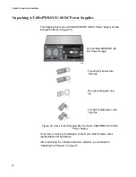
Figure 28. Accessory Kit
If any item is missing or damaged, contact your Allied Telesis sales
representative for assistance.
6. After unpacking the switch, do one of the following:
To unpack the power supplies, go to “Unpacking AT-
SBxPWRSYS2 AC Power Supplies” on page 75 or “Unpacking AT-
SBxPWRSYS1-80 DC Power Supplies” on page 76.
Otherwise, go to Chapter 4, “Installing the Chassis” on page 77.
One 2 m (6.6 ft) local management
cable with RJ-45 (8P8C) and DB-9 (D-
sub 9-pin) connectors.
Two power cord retaining clips
Содержание AT-FAN08
Страница 10: ...Figures 10...
Страница 12: ...Tables 12...
Страница 16: ...Preface 16...
Страница 38: ...Chapter 1 Overview 38...
Страница 60: ...Chapter 2 Virtual Chassis Stacking 60...
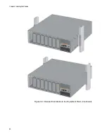
Страница 80: ...Chapter 4 Installing the Chassis 80 Figure 32 Chassis Orientations in the Equipment Rack Continued...
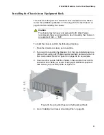
Страница 82: ...Chapter 4 Installing the Chassis 82 Figure 34 Example of Adjusting the Equipment Rack Brackets...
Страница 104: ...Chapter 4 Installing the Chassis 104...
Страница 140: ...Chapter 5 Powering On the Chassis 140...
Страница 166: ...Chapter 7 Cabling the AT XEM2 Line Card Ports 166...
Страница 214: ...Appendix A Technical Specifications 214...


