background image

IT 


INDICE 


SEZIONE 1 — MANUALE USO E MANUTENZIONE                                                          pag.  9 

SEZIONE 2 — LISTA RICAMBI E ESPLOSO                                                                   pag. 31      

ALLEGATO I — SCHEMA ELETTRICO                                                                            


GB


INDEX 


SECTION 1 — OPERATING AND MAINTENANCE INSTRUCTIONS                                     pag. 12      

SECTION 2 — SPARE PARTS LIST AND EXPLODED VIEW                                               pag. 31      

ANNEXE I — ELECTRICAL SCHEME                                                                              


FR


INDEX 


SECTION 1 — MODE D’EMPLOI ET ENTRETIEN                                                             pag. 15      

SECTION 2 — LISTE DES PIECES DETACHEES ET VUE ECLATEE                                     pag. 31      

ANNEXE I — SCHEMA ELECTRIQUE                                                                             


DE


INHALT 


ABSCHNITT 1 — BEDIENUNGS- UND WARTUNGSANLEITUNGEN                                    pag. 19      

ABSCHNITT 2 — ERSATZTEIL-LISTE UND EXPLOSIONSZEICHNUNG                               pag. 31      

ANLAGE I — ELEKTRISCHER SCHALTPLAN                                                                    


NL


INDEX 


DEEL 1 — HANDLEIDING VOOR GEBRUIK EN ONDERHOUD                                      pag. 23 

DEEL 2 — ONDERDELENLIJST EN VERGROTE TEKENING                                          pag. 31      

BIJLAGE I — ELEKTRISCH SCHEMA 


ES


INDICE 


SECCION 1 — MANUAL DE USO Y MANTIENIENTO                                                        pág. 27      

SECCION 2 — LISTA DE LOS REPUESTOS Y DIBUJO DESARROLLADO                             pág. 31      

ALEGATO I — ESQUEMA ELECTRICO                                                                                            

6/37 

Содержание RI1000/25

Страница 1: ...gium Tel 32 56 41 20 54 Fax 32 56 41 86 74 info alliancels eu www alliancels eu RI1000 25 RI1200 25 RI1400 25 Manual Operating maintenance instructions Mode d emploi et entretien Bedienungs und Wartungsanleitungen Instructies voor gebruik en onderhoud Part No D1096 ...

Страница 2: ...Data emissione 14 07 2004 Data approvazione 14 07 2004 Revisione 0 Note 2 37 ...

Страница 3: ...Puissance de chauffage Heizleistung Verwarmend vermogen Potencia de caletamiento kW 6 kW 6 9 kW 7 5 Potenza totale Total power Puissance total Gesamtleistung Totaal vermogen Potencia total kW 6 18 kW 7 09 kW 7 68 Alimentazione Electrical supply Alimentation életrique Netzspannung Voeding Suministro de corriente V 230 3 N 50Hz V 400 3 N 50Hz V 230 3 N 50Hz V 400 3 N 50Hz V 230 3 N 50Hz V 400 3 N 50...

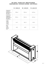
Страница 4: ...00 25 Dimensione A Dimension A Dimension A Abmessungen A Omvang A Dimensione A 1080 mm 1280 mm 1480 mm Dimensione B Dimension B Dimension B Abmessungen B Omvang B Dimensione B 1440 mm 1640 mm 1840 mm Volume Volume Volume Volumen Volume Volumen 0 6 m3 0 69 m3 0 76 m Peso Weight Poids Gewicht Gewicht Peso kg 94 kg 100 kg 106 4 37 ...

Страница 5: ...MANUALE USO E MANUTENZIONE OPERATING AND MAINTENANCE INSTRUCTIONS MODE D EMPLOI ET ENTRETIEN BEDIENUNGS UND WARTUNGSANLEITUNGEN HANDLEIDING VOOR GEBRUIK EN ONDERHOUD MANUAL DE USO Y MANTIENIMENTO 5 37 ...

Страница 6: ...N 2 LISTE DES PIECES DETACHEES ET VUE ECLATEE pag 31 ANNEXE I SCHEMA ELECTRIQUE DE INHALT ABSCHNITT 1 BEDIENUNGS UND WARTUNGSANLEITUNGEN pag 19 ABSCHNITT 2 ERSATZTEIL LISTE UND EXPLOSIONSZEICHNUNG pag 31 ANLAGE I ELEKTRISCHER SCHALTPLAN NL INDEX DEEL 1 HANDLEIDING VOOR GEBRUIK EN ONDERHOUD pag 23 DEEL 2 ONDERDELENLIJST EN VERGROTE TEKENING pag 31 BIJLAGE I ELEKTRISCH SCHEMA ES INDICE SECCION 1 MAN...

Страница 7: ...NCIPAL PEDALIERA PEDAL PEDALIER PEDAL PEDAAL PEDAL PULSANTE STOP SWITCH STOP POUSSOIR STOP STOP SCHALTER STOP SCHAKELAAR PULSADOR STOP PULSANTE START SWITCH START POUSSOIR START START SCHALTER START SCHAKELAAR PULSADOR START SPIA LUMINOSA RESISTENZE HEATING ELEMENTS WARNING LIGHT LAMPE TEMOIN RESISTANCES KONTROLLAMPE FUR HEIZWIDERSTÄNDE CONTROLELAMPJE VOOR WEERSTANDEN LUZ TESTIGO RESISTENCIAS VISU...

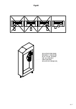
Страница 8: ...Fig 03 VOLANTINO EMERGENZA EMERGENCY HANDWHEEL PETIT VOLANT URGENCE NOT AUS HANDRAD NOODHANDWIEL VOLANTE DE EMERGENCIA 8 37 ...

Страница 9: ...no a carico dell utilizzatore Collegare la stiratrice a terra tramite l apposito morsetto incluso nel quadro elettrico L impianto di terra dovrà essere conforme alle normative di legge Il Costruttore declina ogni responsabilità qualora questa norma antinfortunistica non venga rispettata Verificare che il rullo giri in senso orario In caso di errato collegamento premendo la pedaliera un microinterr...

Страница 10: ...ntino L operatore che compie questo intervento deve precedentemente aver disinserito l interruttore differenziale posto a monte della macchina La superficie del rullo deve essere sfruttata correttamente vedi fig 3 per mantenere omogenea la circonferenza del rullo su tutta la superficie e per una distribuzione ottimale della temperatura Si evitano così ingiallimenti del prodotto stirato ed un calo ...

Страница 11: ...con una inclinazione di 30 gradi circa tenendolo ben teso 3 Iniziare l avvolgimento con la conca in pressione senza accavallare le spire fino al lato destro quindi stendere un secondo strato verso sinistra Proseguire nell operazione fino al raggiungimento della circonferenza di mm 770 4 Posizionare il mollettone ben disteso e metterlo in pressione con la conca fino alla fine dell avvolgimento Nel ...

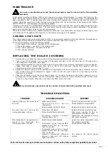
Страница 12: ...arthing system must comply with legal requirements The manufacturer cannot be held responsible should this accident prevention regulation not be observed Ensure that the ironer roller turns clockwise currently In the event of incorrect connection upon pressing the foot pedal control any excessive reverse rotation activates a microswitch pos 27 thus preventing any mechanical displacement To neutral...

Страница 13: ... exact position of the handwheel as soon as you receive your ironer The operator carrying out this procedure should have first turned off the differential switch fitted between the mains outlet and the machine The roller surface must be correctly utilised see fig 3 in order to keep the surface even over the whole circumference of the roller and to obtain optimum temperature distribution In this wa...

Страница 14: ...ards the right hand end with the ironing plate under pressure taking care not to overlap the edges then take a second layer from right to left in the same way Repeat this operation until the circumference of the roller reaches 770 mm 4 Spread the flannel evenly over the padded roller and tighten with the ironing plate under pressure until it is fully wound Raise the temperature to approx 130 C and...

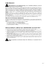
Страница 15: ...erre par l intermédiaire de la borne spéciale incorporée dans le tableau électrique L installation de mise à la terre doit être conforme aux normes en vigueur Le Constructeur décline toute responsabilité en cas de non respect de cette norme concernant la prévention des accidents S assurer que le rouleau tourne bien dans le sens des aiguilles d une montre En cas de branchement erroné en appuyant su...

Страница 16: ...r qui accomplit cette intervention doit avoir préalablement débranché l interrupteur différentiel situé en amont de la machine La surface du rouleau doit être utilisée de manière correcte voir fig 3 afin de maintenir la circonférence du rou leau homogène sur toute la surface et garantir une distribution optimale de la température Ceci permet d éviter le jaunissement du linge repassé ainsi qu une d...

Страница 17: ...ment à nos spécifications en ce qui concerne les performances l exactitude du profil des pièces et les matériaux et présentent toutes les caractéristiques correspondant à nos machines Quand vous commandez des pièces de rechange veuillez nous préciser 1 le nom de la machine voir la plaquette signalétique 2 son numéro de matricule voir la plaquette signalétique 3 le code de la pièce de rechange voir...

Страница 18: ...uté et vérifier la cause de l intervention Attendre le rétablissement du contact de la sonde thermique Débrancher le dispositif d urgence et appuyer sur le pédalier Après avoir réglé la température à l aide du thermostat la presse ne chauffe pas Thermostat de sécurité activé Sonde débranchée le display visualise Er1 pour la droite Er3 pour la gauche Sonde en court circuit le display visualise Er2 ...

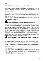
Страница 19: ...bel unterliegen der Verantwortung des Anwenders und gehen zu seinen Lasten Die Mangel mit Hilfe der entsprechenden Klemmen auf der elektrischen Schalttafel an die Erdungsanlage anschließen Die Erdungsanlage muss den geltenden Normen und Gesetzesbestimmungen entsprechen Der Hersteller lehnt jegliche Verantwortung ab wenn diese Unfallverhütungsvorschriften nicht beachtet werden Überprüfen dass die R...

Страница 20: ...end den Sitz dieses Handrades ausfindig machen Der Bediener der diesen Eingriff durchführt muss vorab den der Maschine vorgeschalteten Trennschalter aus schalten Die Walzenoberfläche ist korrekt auszunutzen siehe Fig 3 um die Kontaktfläche der Walze über die gesamte O berfläche gleichmäßig zu halten und um eine optimale Temperaturverteilung zu erzielen Auf diese Weise werden Vergilbungen des Mange...

Страница 21: ...ührung die Formen und das Material betrifft wobei alle Anforderungen an unsere Bügelmaschinen berücksichtigt werden Bei der Bestellung von Ersatzteilen folgendes angeben 1 die Bezeichnung der Maschine siehe Daten des Typenschilds 2 die Seriennummer siehe Daten der Typenschilds 3 für die Artikelnummern des Ersatzteile siehe Ersatzteilliste 4 die Menge pro Stück AUSWECHSELN DER ROLLENBESCHICHTUNG 1 ...

Страница 22: ...alls überprüfen Warten damit das Kontakt der Fühler sich wiederherstellt D i e N o t A u s V o r r i c h t u n g ausschalten und das Pedal betätigen Nach der Einstellung der Temperatur mit Hilfe des Thermostaten heiz sich die Mulde nicht auf Auslösung des Sicherheits Thermostaten Thermostat Fühler ist nicht angeschlossen das Display veranschaulicht Er1 für die rechte Er3 für die linke Thermostat F...

Страница 23: ...van de daarvoor bestemde klem die op het schakelpaneel zit De aardschakeling dient conform de voorschriften van de wet te zijn De constructeur kan niet aansprakelijk worden gesteld indien deze veiligheidsnorm niet gerespecteerd wordt Controleer of de rol met de klok meedraait door Hiermee wordt voorkomen dat de rollen in tegengestelde richting gaan draaien Druk in het geval van onjuiste aansluitin...

Страница 24: ...n de rechterzijde van de strijkmachine zie fig 3 totdat het verwarmingselement los van de rol is Bekijk vooraf de ligging van het handwiel Het oppervlak van de rol moet correct gebruikt worden zie fig 3 om de omtrek van de rol over het gehele oppervlak gelijk te houden en voor een optimale distributie van de temperatuur Zo wordt voorkomen dat de gestreken producten vergelen en dat het rendement pe...

Страница 25: ...angstukken voldoen exact aan onze voorschriften qua uitvoering correctheid van de figuren en het materiaal en voldoen dus aan alle vereisten van onze strijkmachines Om de vervangstukken te bestellen specificeren 1 benaming van de machine zie gegevens van het typeplaatje 2 registratienummer zie gegevens van het typeplaatje 3 de code van het vervangstuk zie lijst van vervangstukken 4 de benodigde ho...

Страница 26: ...e oorzaak van de ingreep na Wacht een paar minuten voor het herstel van het contact van de sensor Schakel de noodinrichting uit en druk het pedaal in Na de temperatuur ingesteld te hebben met de thermostaat verwarmt het verwarmingselement niet Ingreep van de veiligheids thermostaat Sensor is losgekoppeld de display geeft Er1 voor rechts en Er3 voor links aan Kortsluiting sensor de display geeft Er...

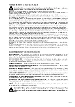
Страница 27: ...ión son a cargo del usuario Poner a tierra la planchadora mediante el borne apropiado incluido en el tablero eléctrico La instalación de tierra tendrá que cumplir la normativas de la ley El Fabricante no se hace responsable de ninguna manera en el caso de que esta norma de prevención de accidentes no sea respetada Compruebe que el rodillo gira en sentido horario En el caso de haber hecho una conex...

Страница 28: ...l operador que realiza esta operación tiene que haber desconectado precedentemente el interruptor diferencial colocado antes de la máquina La superficie del rodillo tiene que ser aprovechada correctamente véase fig 3 para mantener homogénea la circunferencia del rodillo en toda su superficie y para obtener una óptima distribución de la temperatura De esta manera se evita que se ponga amarillo el p...

Страница 29: ...estras prescripciones en lo referente a ejecución exactitud de las figuras y material y por lo tanto cumplen todos los requisitos requeridos por nuestras planchadoras Al pedir piezas de repuesto especifique 1 la denominación de la máquina véase los datos de la chapa 2 el número de matrícula véase los datos de la chapa 3 el código del repuesto véase lista de los repuestos 4 la cantidad de cada piez...

Страница 30: ...lgunos minutos que la sondea ripristini el contacto Deshabilitar el dispositivo de emergencia y pisar el pedal Después de haber regulado la temperatura por medio del termóstato el cuenco no se calienta Se acciona el termóstato de seguridad Sonda desconectada en el display aparece Er1 para la derecha Er3 para la izquierda Sonda en cortocircuito en el display aparece Er2 para la derecha Er4 para la ...

Страница 31: ...BI E ESPLOSO SPARE PARTS LIST AND EXPLODED VIEW LISTE DE PIECES DETACHEES ET VUE ECLATEE ERSATZTEIL LISTE UND EXPLOSIONZEICHNUNG ONDERDELENLIJST EN VERGROTE TEKENING LISTA DE REPUESTOS Y DIBUJO DESARROLLADO 31 37 ...

Отзывы: