3-16
SECTION 3
SERVICE
053430; 01/11
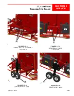
The dolly jack lifting system is designed for short moves and
to aid in servicing the trowel. It is not a substitute for a
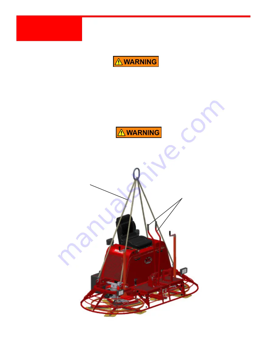
towing system or trailer. An optional lifting bridle
[N]
is available and recommended for lifting the trowel.
Attach the bridle to each of the four lifting eyes
[O]
on the trowel. Refer to Figure 3.7.7.
Secure steering levers to frame to prevent them
from tipping forward when the towel is
being lifted.
3.7, continued
Transporting Trowel
FIGURE 3.7.6
LIFTING BRIDLE
[N]
STEERING LEVERS
VISUAL REPRESENTATION
Содержание MSP445
Страница 1: ...OPERATIONS PARTS MANUAL MSP445 RIDING TROWEL REVISION 05 2018 MANUAL PART 053430 ...
Страница 17: ...1 1 053430 01 11 Section 1 SAFETY Section 1 SAFETY ...
Страница 29: ...2 1 053430 01 11 SECTION 2 OPERATIONS Section 2 OPERATIONS ...
Страница 38: ...2 10 SECTION 2 OPERATIONS 053430 01 11 Notes ...
Страница 39: ...3 1 053430 01 11 SECTION 3 SERVICE Section 3 SERVICE ...
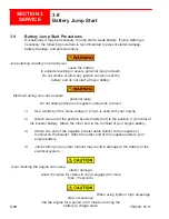
Страница 57: ...3 19 053430 01 11 SECTION 3 SERVICE 3 8 continued Battery Jump Start FIGURE 3 8 1 BATTERY LOCATION BATTERY ...
Страница 60: ...3 22 SECTION 3 SERVICE 053430 01 11 Notes ...
Страница 61: ...4 1 053430 1 11 4 1 053430 1 11 Section 4 PARTS Section 4 PARTS ...
Страница 64: ...4 4 053430 1 11 4 4 Section 4 PARTS 053430 1 11 4 1 Illustration Front View Upper Frame Unit 1 4 2 3 5 ...
Страница 66: ...4 6 053430 1 11 4 6 Section 4 PARTS 053430 1 11 4 2 Illustration Rear View Upper Frame Unit 3 4 1 2 5 6 ...
Страница 68: ...4 8 053430 1 11 4 8 Section 4 PARTS 053430 1 11 4 3 Illustration Instrumentation Control System 1 ...
Страница 74: ...4 14 053430 1 11 MSP445 Frame Pre 9 2013 048838 MSP445 Frame Post 9 2013 060891 Frame Design ...
Страница 75: ...4 15 053430 1 11 4 6 Illustration Fuel System 1 2 4 5 8 9 10 11 11 10 12 13 6 7 14 ...
Страница 77: ...4 17 053430 1 11 4 7 Illustration Electrical System 2 1 3 3 3 5 6 7 8 3 4 11 12 13 ...
Страница 79: ...4 19 053430 1 11 4 8 Illustration Steering System 17 19 3 4 5 21 22 20 9 14 15 14 15 13 12 13 13 11 10 18 ...
Страница 83: ...4 23 053430 1 11 4 10 Illustration Pitch Control Assembly 2 4 7 8 ...
Страница 87: ...4 27 053430 1 11 4 12 Illustration Engine System 1 2 3 4 ...
Страница 89: ...4 29 053430 1 11 4 13 Illustration Engine Mounting System 6 23 18 12 7 27 20 26 17 9 14 13 10 22 21 A 28 ...
Страница 91: ...4 31 053430 1 11 4 14 Illustration Driveline System 13 5 3 8 6 9 14 10 10 1 7 2 12 11 ...
Страница 93: ...4 33 053430 1 11 4 15 Illustration Throttle Control System 1 2 4 7 3 6 5 ...
Страница 95: ...4 35 053430 1 11 4 16 Illustration Oil Drain System 2 1 ...
Страница 101: ...4 41 053430 1 11 4 20 Illustration Right Hand Spider Assembly 1 5 2 4 11 10 7 6 9 8 ...
Страница 103: ...4 43 053430 1 11 4 21 Illustration Left Hand Spider Assembly 1 3 2 4 7 5 8 9 10 6 11 ...
Страница 109: ...4 49 053430 1 11 4 24 Illustration Front View Identification and Marking Decals 4 8 6 5 3 8 7 1 10 9 ...
Страница 111: ...4 51 053430 1 11 4 25 Illustration Rear View Identification and Marking Decals 12 11 6 2 ...
Страница 115: ...4 55 053430 1 11 4 27 Illustration Accessory Non standard Items 2 1 ...
Страница 117: ...4 57 053430 1 11 4 28 Illustration Tools Service 1 2 ...

