background image

38

Rockwell Automation Publication 2711P-UM006A-EN-P - November 2010

Chapter 3

        Connect Power

Connect AC Power

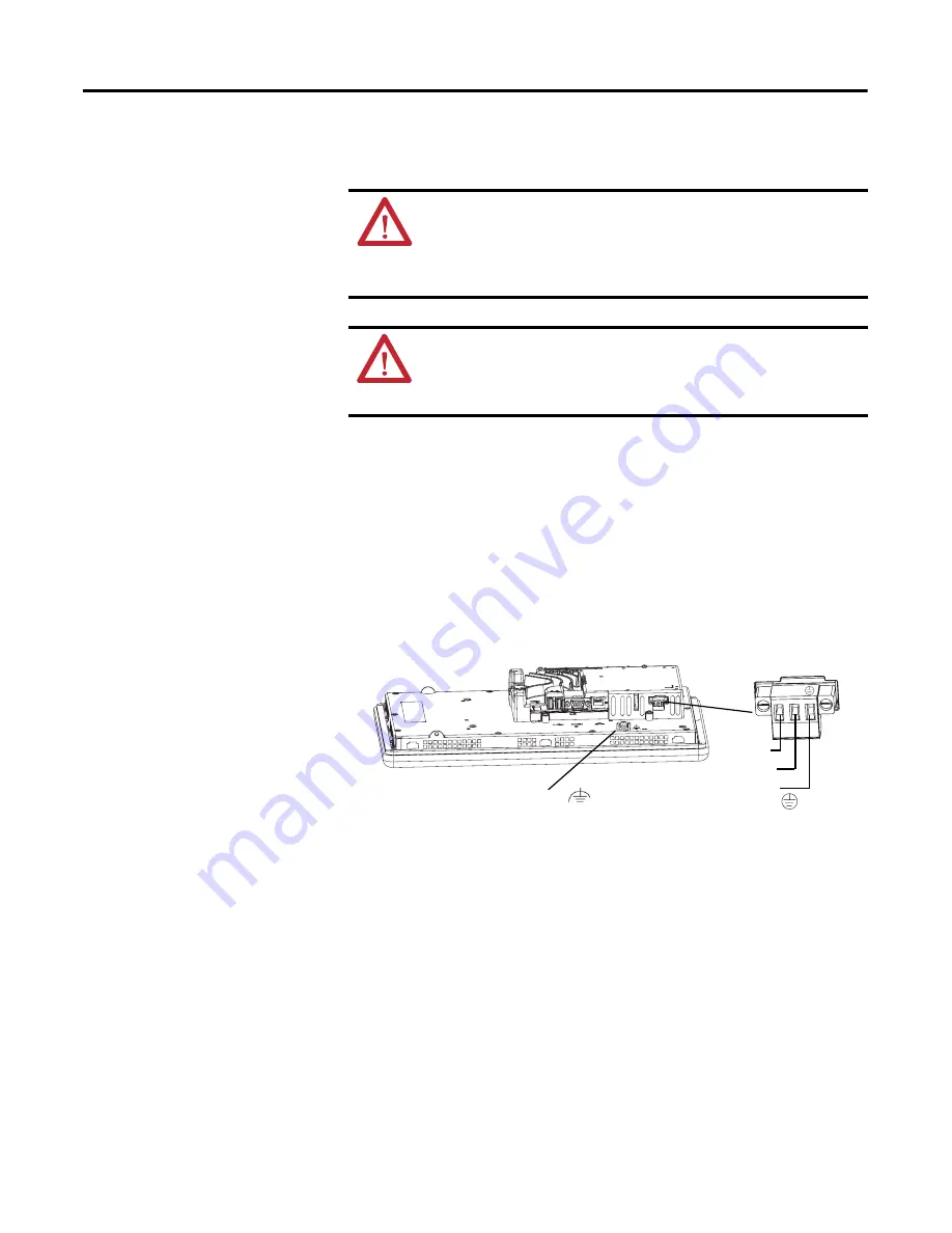
Follow these steps to connect the terminal to AC power.

1.

Verify that the terminal is not connected to a power source.

2.

Secure the AC power wires to the terminal block.
Follow the markings on the terminal block and terminal for proper 
connections.

3.

Secure the protective earth/ground wire to the marked position of the 
power input terminal block.

4.

Secure the functional earth/ground wire to the functional earth terminal 
screw on the back of the display to ground bus.

5.

Apply power to the terminal.


WARNING: 

Explosion Hazard

Do not disconnect equipment unless power has been switched off and 
area is known to be nonhazardous.

Disconnect all power before installing or replacing components. Failure to 
disconnect power may result in electrical shock or damage to the terminal.

ATTENTION: 

Improper wiring of the power terminals may result in 

voltage at the communication connector shells. 

Do not apply power to the terminal until all wiring connections have been 
made. Failure to do so may result in electrical shock.

L1

L2/Neutral

Protective Earth 
to Ground Bus

Functional Earth/Ground 

L1 L2N

to Ground Bus

Содержание PanelView Plus 6 1000

Страница 1: ...User Manual PanelView Plus 6 Terminals 700 1000 1250 1500 Catalog Numbers 2711P Kxxxx8 2711P Txxxx8 2711P Bxxxx8 2711P Kxxxx9 2711P Txxxx9 2711P Bxxxx9 ...

Страница 2: ... or software described in this manual Reproduction of the contents of this manual in whole or in part without written permission of Rockwell Automation Inc is prohibited Throughout this manual when necessary we use notes to make you aware of safety considerations Allen Bradley CompactLogix ControlLogix FactoryTalk View Machine Edition FactoryTalk View Studio FactoryTalk ViewPoint PLC 5 PanelView D...

Страница 3: ...nal Selections 17 Module Selections 19 Accessories 20 Chapter 2 Install Terminal Chapter Objectives 23 Environment and Enclosure Information 23 North American Hazardous Location Approval 24 USB Ports 25 Outdoor Installation for High bright Displays 26 Using an Antiglare Overlay 27 Using a Solar Visor 27 Selecting an Enclosure 27 Backlight Considerations 27 Orientation of the Terminal 27 Required T...

Страница 4: ...esktop Access 50 Enable Desktop Access 50 Disable Desktop Access 51 Set a Desktop Password 52 Reset the Desktop Password 53 Communication Setup 54 Configure KEPServer Serial Port ID s 54 Configure RSLinx Communication Properties 54 Configure a Device Address 56 Ethernet Network Connections 56 Set the Ethernet IP Address for the Terminal 56 Set the Ethernet Link Speed 58 Define Name Server Addresse...

Страница 5: ... and Date Settings 76 Change the Date for Terminal Operations 76 Change the Time for Terminal Operations 76 Change the Time Zone for Terminal Operations 77 Regional Settings 78 Select a Language 78 Change the Decimal Separator for Numeric Formats 78 Change the Time Format for a Language 79 Change the Short Date Format for a Language 80 Change the Long Date Format for a Language 81 Font Linking 82 ...

Страница 6: ...Parameters 99 Chapter 6 Install and Replace Components Chapter Objectives 101 Required Tools 101 Precautions 101 Install or Replace the Logic Module 102 Install or Replace a Communication Module 103 Replace the Display Module 105 Replace the Bezel 106 Remove the Display Module Bezel 106 Replace the Display Module Bezel 108 Replace the Battery 109 Replace the Backlight 111 Remove the Product ID Lab...

Страница 7: ... Cables 131 Module Connection to ControlNet Network 132 Chapter 8 Firmware Upgrades Chapter Objectives 133 Terminal Firmware 133 Download Firmware Files 134 Firmware Upgrade Wizard 134 Upgrading Terminal Firmware from a Storage Device 135 Create a Firmware Upgrade Card 135 Upgrade Terminal Firmware Using Firmware Upgrade Card 137 Upgrade Terminal Firmware over the Network 138 Chapter 9 Troubleshoo...

Страница 8: ...tem Errors 149 Advanced Diagnostics 150 Access Maintenance Operations 151 Appendix A Specifications Technical Specifications 155 Environmental Specifications 157 Certifications 157 Appendix B Fonts Resident on Terminal True Type Fonts 159 Appendix C Virtual Key Codes Key Definitions 161 Index ...

Страница 9: ... concerning related Rockwell Automation products You can view or download publications at http www rockwellautomation com literature To order paper copies of technical documentation contact your local Rockwell Automation distributor or sales representative Firmware Upgrades For the latest firmware upgrades and other downloads for your PanelView Plus 6 terminal go to http www rockwellautomation com...

Страница 10: ...10 Rockwell Automation Publication 2711P UM006A EN P November 2010 Preface Notes ...

Страница 11: ...port and integrates into systems with Rockwell Automation controllers including the preferred Logix controllers Modular components are usable across the entire PanelView Plus 6 platform Display modules range in size from 6 5 to 15 inches with either key touch or combination key touch input Windows CE logic module runs an open or closed desktop environment and offers optional extended features and ...

Страница 12: ...system is configurable via the control panel and supports Windows operations A closed system launches a FactoryTalk View Machine Edition application on startup and does not allow access to the Windows CE desktop All terminals are initially shipped as closed systems restricting access to the desktop The first time you start the system the terminal launches FactoryTalk View ME Station Configuration ...

Страница 13: ... Software Support All PanelView Plus 6 terminals support the same HMI software Table 2 PanelView Plus 6 Software Support TIP All terminals are initially shipped with desktop access disabled IMPORTANT Allowing desktop access does not change the feature set of your terminal For example If you have a PanelView Plus 6 terminal without extended features opening the desktop will not give you access to t...

Страница 14: ...h screen input 700 6 5 in 1000 10 4 in 1250 12 1 in 1500 15 in Display modules are also available with these characteristics Marine certified Conformal coated High bright display for outdoor use Built in antiglare overlay 2 Logic module The logic modules has these hardware features Power input AC or DC RS 232 serial port Ethernet port 2 USB 2 0 host ports 1 high speed device port Network interface...

Страница 15: ...DC power input 1 Isolated 18 32V DC 85 264V AC 1 For DC applications using AC power an external remote AC to DC power supply cat no 2711P RSACDIN is available for DIN rail mounting 3 10 100 BaseT Auto MDI MDI X Ethernet port for logic controller communication 4 Serial RS 232 port for file transfers printing and logic controller communication 5 2 USB host ports for attaching USB devices including m...

Страница 16: ...field replaceable bezels Figure 2 Display Modules 5 4 3 1 2 1 2 IMPORTANT The keypad is designed for finger or gloved finger operation The touch screen may be operated with a finger gloved finger or plastic stylus device with a minimum tip radius of 1 3 mm 0 051 in Using any other object or tool may damage the keypad or touch screen Table 5 Display Features Item Feature Description 1 Replaceable I...

Страница 17: ...Table 6 PanelView Plus 6 Terminals Cat Nos Display Communication Input Power Nonvolatile Flash RAM Memory 2 Keypad Touch Keypad Touch Size Type RS 232 Ethernet 700 Model 2711P K7C4D8 2711P T7C4D8 2711P B7C4D8 6 5 in Color DC 512 MB 512 MB 2711P T7C4D8K 1 DC 512 MB 512 MB 2711P K7C4A8 2711P T7C4A8 2711P B7C4A8 AC 512 MB 512 MB 1000 Model 2711P K10C4D8 2711P T10C4D8 2711P B10C4D8 10 4 in Color DC 51...

Страница 18: ...D9 2711P T10C4D9 2711P B10C4D9 10 4 in Color DC 512 MB 512 MB 2711P K10C4A9 2711P T10C4A9 2711P B10C4A9 AC 512 MB 512 MB 1250 Model 2711P K12C4D9 2711P T12C4D9 2711P B12C4D9 12 1 in Color DC 512 MB 512 MB 2711P K12C4A9 2711P T12C4A9 2711P B12C4A9 AC 512 MB 512 MB 1500 Model 2711P K15C4D9 2711P T15C4D9 2711P B15C4D9 15 in Color DC 512 MB 512 MB 2711P K15C4A9 2711P T15C4A9 2711P B15C4A9 AC 512 MB 51...

Страница 19: ...T7CK Touch 2711P RDT7CM Touch 2711P RDB7C Keypad Touch 2711P RDB7CK Keypad Touch 2711P RDB7CM Keypad Touch 1000 Model 2711P RDK10C Keypad 10 4 in color 2711P RDT10C Touch 2711P RDT10CM Touch 2711P RDB10C Keypad Touch 2711P RDB10CM Keypad Touch 1250 Model 2711P RDK12C Keypad 12 1 in color 2711P RDK12CK Keypad 2711P RDT12C Touch 2711P RDT12CK Touch 2711P RDT12H 1 1 H at end of cat no refers to 1250 ...

Страница 20: ...nterface communication module Windows CE 6 0 operating system with extended features and file viewers FactoryTalk View Machine Edition runtime version 6 0 or later FactoryTalk ViewPoint software version 1 2 or later 2711P RP9D DC 512 MB 512 MB 2711P RP9DK DC 512 MB 512 MB Table 10 Communication Modules Cat No Communication Conformal Coated Marine Certified DH DH 485 ControlNet 1 1 Scheduled and un...

Страница 21: ...l Model Operator Input Keypad Touch Key Touch 2711P RGK7 700 2711P RGT7 2711P RGK10 1000 2711P RGT10 2711P RGK12 1250 2711P RGT12 2711P RGK15 1500 2711P RGT15 Table 15 Solar Visor Cat No Description 2711P RVT12 Solar visor for 1250 high bright display module cat no 2711P RDT12H Table 16 Mounting Hardware Cat No Description Quantity 2711P RTMC Mounting clips 8 Table 17 Programming Cable Cat No Desc...

Страница 22: ...P RAK7 700 keypad or keypad touch PanelView Standard 900 keypad 2711P RAT7 700 touch PanelView Plus 900 touch 2711P RAK10 1000 keypad or keypad touch PanelView 1000 1000e keypad 2711P RAT10 1000 touch PanelView 1000 1000e touch 2711P RAK15 1500 keypad or keypad touch PanelView 1200e 1400e keypad 2711P RAT15 1500 touch PanelView 1200e 1400e touch 2711P RAK12E 1250 keypad 1 1 Applies also to PanelVi...

Страница 23: ...ential and other environments due to conducted or radiated disturbances Korean Radio Wave Suitability Registration When so marked this equipment is registered for Electromagnetic Conformity Registration as business equipment A not home equipment Sellers or users are required to take caution in this regard This equipment is supplied as open type equipment It must be mounted within an enclosure that...

Страница 24: ... de température pour les environnements dangereux Lorsque plusieurs produits sont combinés dans un système le code de température le plus défavorable code de température le plus faible peut être utilisé pour déterminer le code de température global du système Les combinaisons d équipements dans le système sont sujettes à inspection par les autorités locales qualifiées au moment de l installation W...

Страница 25: ...onincendive field wiring apparatus for use in hazardous locations shall be coordinated with the associated nonincendive field wiring apparatus such that their combination remains nonincendive The PanelView Plus 6 terminals and the USB peripheral devices shall be treated in this manner Table 21 PanelView Plus 6 USB Port Circuit Parameters Voc Isc Ca La Groups A and B Groups C and D Groups A and B G...

Страница 26: ...he proper orientation of the terminal Ultraviolet and infrared radiation can reduce the field life of any electronic device While the materials used in the terminal bezels provide long field life that field life can be extended by proper installation Table 23 Symbol Definitions Voc Open circuit voltage of the host USB port Isc Maximum output current of the host USB port Vmax Maximum applied voltag...

Страница 27: ...onents of an enclosure affect the temperature rise inside the cabinet Hoffman a Rockwell Automation Encompass Partner has information to help you select an enclosure and heating cooling accessories to meet the temperature requirements of the installed equipment See http www hoffmanonline com Stirring fans or active cooling may be required in high altitude and high ambient temperature locations to ...

Страница 28: ...ed for ventilation Top clearance 51 mm 2 in Bottom clearance 102 mm 4 in Side clearances 25 mm 1 in Back clearance 25 mm 1 in Minimum side clearance for inserting an SD card is 102 mm 4 in Panel Cutout Dimensions Use the full size template shipped with your terminal to mark the cutout dimensions Terminal Type Height mm in Width mm in 700 Keypad or Keypad and Touch 167 6 57 264 10 39 700 Touch 154 ...

Страница 29: ...or Keypad Touch 290 mm 11 40 in 193 mm 7 58 in 55 mm 2 18 in 83 mm 3 27 in 700 Touch 246 mm 9 68 in 179 mm 7 04 in 55 mm 2 18 in 83 mm 3 27 in 1000 Keypad or Keypad Touch 399 mm 15 72 in 248 mm 9 77 in 55 mm 2 18 in 83 mm 3 27 in 1000 Touch 329 mm 12 97 in 248 mm 9 77 in 55 mm 2 18 in 83 mm 3 27 in 1250 Keypad or Keypad Touch 416 mm 16 36 in 282 mm 11 12 in 55 mm 2 18 in 83 mm 3 27 in 1250 Touch 3...

Страница 30: ...n the terminal This gasket forms a compression type seal Do not use sealing compounds Be careful not to pinch the legend strip during installation 3 Place the terminal in the panel cutout 4 Slide the ends of the mounting clips into the slots on the terminal ATTENTION Disconnect all electrical power from the panel before making the panel cutout Make sure the area around the panel cutout is clear Ta...

Страница 31: ... lb in by using the specified sequence making sure not to overtighten ATTENTION Tighten the mounting clips to the specified torque to provide a proper seal and to prevent damage to the product Allen Bradley assumes no responsibility for water or chemical damage to the product or other equipment within the enclosure because of improper installation 1 2 3 4 5 6 7 8 Torque Sequence for 6 Clips 2 4 6 ...

Страница 32: ...32 Rockwell Automation Publication 2711P UM006A EN P November 2010 Chapter 2 Install Terminal Notes ...

Страница 33: ...rotect the input power by a fuse or circuit breaker rated at no more than 15 A Route incoming power to the device by a separate path from the communication lines Cross power and communication lines at right angles if they must cross Communication lines can be installed in the same conduit as low level DC I O lines less than 10V Shield and ground cables appropriately to avoid electromagnetic interf...

Страница 34: ...terminal block 1 Reattach the terminal block to the connector until seated 2 Tighten the two screws that secure the terminal block to the connector WARNING Explosion Hazard Substitution of components may impair suitability for hazardous locations Do not disconnect equipment unless power has been switched off and area is known to be nonhazardous Do not connect or disconnect components unless power ...

Страница 35: ... devices with a DC power input have an earth ground terminal that you must connect to a low impedance earth ground The earth ground connection is on the rear of the display module Table 25 Wire Specifications for DC Input Power Terminal Block Wire Type Dual wire Gauge 1 1 Two wire max per terminal Single wire Gauge Terminal Screw Torque Stranded or solid Cu 90 C 194 F 0 3 1 3 mm2 22 16 AWG 0 3 2 1...

Страница 36: ...arth ground terminal screw at the bottom of the display 4 Apply power to the terminal Table 26 Earth Ground Wire Specifications for DC Power Symbol Wire Type Wire Gauge Terminal Screw Torque GND Stranded or solid Cu 90 C 194 F 2 1 5 3 mm2 14 10 AWG 1 13 1 36 N m 10 12 lb in ATTENTION Damage or malfunction can occur when a voltage potential exists between two separate ground points Make sure the te...

Страница 37: ...e Type Dual wire Gauge 1 1 Two wire max per terminal Single wire Gauge Terminal Screw Torque Stranded or solid Cu 90 C 194 F 0 3 1 3 mm2 22 16 AWG 0 3 2 1 mm 22 14 AWG 0 56 N m 5 lb in ATTENTION The functional earth and protective earth connections to ground are mandatory The functional earth ground connection is required for electromagnetic compliance EMC with the EU European Union EMC directive ...

Страница 38: ...e functional earth terminal screw on the back of the display to ground bus 5 Apply power to the terminal WARNING Explosion Hazard Do not disconnect equipment unless power has been switched off and area is known to be nonhazardous Disconnect all power before installing or replacing components Failure to disconnect power may result in electrical shock or damage to the terminal ATTENTION Improper wir...

Страница 39: ...owing Launch FactoryTalk Machine Edition and run an HMI application that is configured to run at startup Launch FactoryTalk View Machine Edition and run the configuration options for the terminal default shown above Launch the Windows Explorer desktop All PanelView Plus 6 terminals can also be configured to allow desktop access Terminals are initially shipped with desktop access disabled To allow ...

Страница 40: ...ns configuration options for the terminal Launches the Windows Explorer desktop shell The action that occurs depends on the startup options configured for your terminal Refer to Startup Options on page 47 for details Refer to Start up Messages and Codes on page 144 for a list of startup information and error messages To reset the terminal insert a thin nonconductive probe into the hole marked rese...

Страница 41: ...Edition mer application is set to run closed system From Windows Explorer desktop you can access the Configuration mode of the terminal by double clicking the FactoryTalk View ME Station icon on the desktop Topic Page Topic Page Access Configuration Mode 41 Configure Print Options 68 Terminal Settings 44 Check Integrity of Application Files 70 Load and Run Application 46 Configure Diagnostics 71 S...

Страница 42: ... shortcuts defined for the loaded mer application Device shortcuts are read only and cannot be edited For example your MER application might have CLX defined as a device shortcut name for a ControlLogix controller Terminal Settings F4 Opens a menu of options to configure non application terminal settings for the PanelView Plus 6 device Delete Log Files Before Running F5 Toggles between Yes and No ...

Страница 43: ...ed click a key 2 Press the Select button to copy the character to the display area 3 Press Enter when done to exit the input panel Display Area Character Keyboard Controls Table 31 Input Panel Controls Input Panel Controls Function SHF Switches keys between their shifted and unshifted state The initial default is shifted CAPS Switches keys between lowercase and uppercase characters The initial def...

Страница 44: ...sword File Management Copies or deletes application files and font files from the terminal by using an SD card or a USB flash drive You can also delete all FactoryTalk View ME Station log files Font Linking Links a font file to a base font loaded on the terminal Input Devices Configures settings for the keypad touch screen or attached keyboard and mouse including touch screen calibration Also lets...

Страница 45: ...page 73 page 47 Diagnostics Setup page 71 Display File Management page 82 System Event Log page 72 Display Temperature Copy Applications page 62 page 62 Copy Fonts Copy Files Delete Files page 65 Keyboard Keypad Mouse Calibrate Touch Screen page 66 page 67 Double Tap Sensitivity Touch Screen page 65 page 66 String Popup KEPServer Serial Port IDs Ethernet Network Connections Network Identification ...

Страница 46: ...you want to replace the terminal s communication configuration with the configuration in the application 5 Select Yes or No If you select Yes any changes to the device addresses or driver properties in the RSLinx Communications dialog will be lost The name of the currently loaded application will appear at the top of the main Configuration mode dialog 6 Press the Run button on the Configuration mo...

Страница 47: ... On Startup button until Do not start FactoryTalk View ME is selected 3 Press OK This Start up Option Performs This Action Typical System Do not start FactoryTalk View ME Station Launches the Windows Explorer desktop on startup Open Go to Configuration Mode Launches FactoryTalk View ME Station Configuration mode on startup This is the initial factory default setting Closed Run Current Application ...

Страница 48: ...ent Application button to specify whether you want to load the current application on startup 5 Press the Replace RSLinx Communications button to specify whether to use the communication configuration of the current application or that of the terminal on startup Select No to use the RSLinx configuration of the terminal Select Yes to use the configuration of the application The terminal configurati...

Страница 49: ... what configuration settings to use when running the application Select No to use the RSLinx configuration of the terminal Select Yes to use the configuration of the application The terminal configuration is replaced with the application settings Any changes to device addresses or driver properties in RSLinx communication will be lost 4 Press the Delete Log Files On Every Power Cycle button to spe...

Страница 50: ...ory with a default password and challenge question that we recommend you change Default password password case sensitive Default challenge question What is the opposite of lock Default challenge answer unlock case sensitive When desktop access is set to allow you can access the desktop by pressing the Exit button from FactoryTalk View ME Station Configuration mode Enable Desktop Access Follow thes...

Страница 51: ...e the startup option You will also be required to enter a password and challenge question The password is required to access the desktop from FactoryTalk View ME Station when pressing the Exit button The challenge question and response will be required to change the password with the Reset Password function Follow these steps to disable desktop access 1 Select Terminal Settings Desktop Access Setu...

Страница 52: ... to enter the response to the challenge question then press Enter 5 Press OK The Desktop Access Management dialog will show that a password and challenge question are set 6 Press OK to return to Terminal Settings IMPORTANT If you disallow or restrict access to the desktop you will be required to set a password along with a challenge question TIP You would have to correctly enter this password befo...

Страница 53: ...password 1 Press the Reset Password button from Desktop Access Management 2 Press the Answer Challenge button and enter the correct response to the current challenge question 3 Press the Clear Password button to clear the current password and challenge question The dialog indicates the password and challenge information is cleared Password status Password is not set Challenge status Challenge is n...

Страница 54: ...Communications KEPServer Serial Port ID s If KEPServer Enterprise is not installed you will get an error message Configure RSLinx Communication Properties Follow these steps to configure driver settings for the communication protocol used by your application 1 Select Terminal Settings Networks and Communications RSLinx Enterprise Communications You will see a tree view of installed cards and netwo...

Страница 55: ...top bits used 1 or 2 Ack Poll Timeout Ack Poll timeout value in ms 20 60 000 ms Max Retries Number of retries before serial driver fails 0 10 Station Number Station number based on a specific device 0 254 COM Port Communication port used on the terminal 1 4 DHPlus Properties Jumper ID Identifies the communication card if multiple cards are installed on terminal 0 3 Station Number The unique addres...

Страница 56: ...ddress and then press the Enter button You return to the previous dialog with the new address 5 Press OK Ethernet Network Connections The terminal has a built in Ethernet driver You can configure this Ethernet information for your terminal IP address of terminal on network including link speed Device name to identify terminal on network Username and password to access network resources Set the Eth...

Страница 57: ...guration mode dialog 5 Press Close Field Description Valid Values Use DHCP Enables or disables Dynamic Host Configuration Protocol DHCP settings DHCP automatically allocates network devices and configurations to newly attached devices on the network If DHCP is set to Yes the terminal is automatically assigned an IP address Subnet Mask and Gateway The fields are disabled If DHCP is set to No you ca...

Страница 58: ... Press the Settings button to view or modify the Ethernet link settings 3 Press the Ethernet Configuration button to select an Ethernet link option for your Ethernet connection The default setting of Auto will automatically sense the link option and speed based on the terminal connection to a network Define Name Server Addresses You can define name server addresses for the EtherNet IP network adap...

Страница 59: ...evice Description button to enter a description for the device 4 Press OK Field Description Valid Values Primary DNS The address of the primary DNS resolver xxx xxx xxx xxx Secondary DNS The address of the secondary DNS resolver xxx xxx xxx xxx Primary WINS The address of the primary WINS resolver xxx xxx xxx xxx Secondary WINS The address of the secondary WINS resolver xxx xxx xxx xxx Field Descr...

Страница 60: ...files that are stored on the terminal Deleting application mer files font files or generated log files Copying application files or font files between storage locations Delete Application File or Font File You can delete FactoryTalk View ME mer files or font files that reside in the internal flash memory of the terminal a loaded USB flash drive or a loaded SD card The procedure for deleting an app...

Страница 61: ...ect a file from the list 4 Press the Delete button 5 Select Yes or No when asked if you want to delete the selected application or font file from the storage location Delete Log Files You can delete generated log files alarm history files and alarm status files from the System Default location on the terminal 1 Select Terminal Settings File Management Delete Files Delete Log Files You are asked to...

Страница 62: ...minal External Storage 1 SD card loaded in the card slot of the terminal External Storage 2 USB flash drive connected to a USB host port 3 Select a file from the storage location 4 Press the Destination button on the same dialog 5 Press the Destination button to choose the location to copy the file The destination must be different than the source location 6 Press the Copy button to copy the selec...

Страница 63: ... select Terminal Settings Display Display Temperature The terminals have a cold cathode fluorescent lamp CCFL backlight This backlight requires temperature control when the internal temperature of the product is below 10 C 50 F or above 60 C 140 F The terminal monitors low and high temperature conditions If the internal temperature is the following Below 10 C 50 F the backlight is set to overdrive...

Страница 64: ...meout for activating the screen saver To disable the screen saver select the Disabled option 3 Increase or decrease the brightness intensity of the screen saver by pressing the up and down cursor buttons 4 Press the Advanced Settings button to access the bitmap option Select the Screen Saver Image button to enable or disable the screen saver bitmap Press OK to return to the previous 5 Press OK to ...

Страница 65: ...ecify the number of times a key is repeated per second when you hold a key down Valid values for the keypad are 0 and 2 30 The keyboard is device dependent but typical values are the same 3 Press the Repeat Delay button to select the amount of time that elapses per second before a key is repeated Values are device dependent Unsupported values are dimmed 4 Press OK when done Set the Sensitivity of ...

Страница 66: ...rate the touch screen 1 Select Terminal Settings Input Devices Touch Screen Calibration 2 Follow the instructions on the screen When the calibration is complete you will see a message that indicates new calibration settings have been measured IMPORTANT Use a plastic stylus device with a minimum tip radius of 1 3 mm 0 051 in to prevent damage to the touch screen On Touch screens Tap the screen to r...

Страница 67: ...cess is identical to setting the double tap sensitivity for the mouse 1 Select Terminal Settings Input Devices Touch Screen Double Tap Sensitivity 2 Double tap the Set button to set the sensitivity of touch screen presses 3 Double tap the Test button to test the sensitivity of touch screen presses If you double tap the test button with the time set using the Set button the Test button will reverse...

Страница 68: ...e printer Printers that do not configure automatically to the appropriate driver can be installed manually Follow these steps to access the print setup 1 Select a Terminal Settings Print Setup option Alarm Print Setup Diagnostic Setup Display Print Setup Print Setup displays installed printers that are available to the FactoryTalk View Machine Edition application The terminals are not shipped with...

Страница 69: ...es 500 messages or timeout period whichever is first 168 hours 7 days If the queue has 350 messages after 168 hours the 350 messages are printed You can change the timeout period Specified number of messages or timeout period whichever is first 60 messages 168 hours 7 days If the queue has 60 messages after 24 hours then the 60 messages are printed You can change the number of messages and the tim...

Страница 70: ...eck 2 Press either of the Enable buttons to enable or disable file integrity checks Enable Check of the MER Enable Check of the Runtime Files By default integrity checks are automatically performed on the application mer file and runtime files If you disable either of these functions the files will not be checked nor will the log file be updated 3 Press OK to save changes Follow these steps to vie...

Страница 71: ... Routing dialog lets you access these dialogs Remote Log FactoryTalk View Diagnostics List Each dialog shows a list of messages that can be sent to that destination The list shows the status of each message type Use the On Off button to turn a message type on or off A message type is enabled if it has a checked box The Audit Message Logging dialog lets you log messages as Audit or Information when...

Страница 72: ...y the terminal The log provides a time stamp of when each event occurred and text describing the event If the event log is full when a new event occurs the oldest entry is removed to accommodate the new event 1 Select Terminal Settings System Event Log 2 Select an event and press the More Details button to display log details for that event 3 Press the Clear All button to clear all system event lo...

Страница 73: ...ded for the terminal Total power on time in minutes Processor temperature Battery voltage and battery state Memory allocated and used on terminal RAM memory used during runtime Follow these steps to display terminal information 1 Select Terminal Settings System Information Terminal Information All fields are read only The CPU temperature should be less than 95 C 203 F The battery voltage must be a...

Страница 74: ...d storage or program memory Amount of storage or program memory in use Amount of available flash memory 3 Press Close to return to previous dialog 4 Press the Runtime RAM Usage button to troubleshoot runtime anomalies by showing the amount of RAM used by your application at runtime 5 Press OK to return to previous dialog 6 Press Close until you return to terminal settings ...

Страница 75: ...rt phone number and website for your terminal 3 Press Close until you return to terminal settings Enable or Disable the Alarm Display Each new alarm that occurs on the terminal is displayed in the alarm display or banner When the newest alarm is acknowledged by the operator you can choose to close the alarm display or leave it open By default the alarm display is closed 1 Select Terminal Settings ...

Страница 76: ...OK when done Change the Time for Terminal Operations Follow these steps to adjust the time for terminal operations 1 Select Terminal Settings Time Date Regional Settings Time The current time appears in 24 hour format in separate Hour Minute and Second fields 2 Press the Hour Minute and Seconds buttons to change the values 3 Press OK when done Field Description Valid Values Year The current year i...

Страница 77: ...upports Daylight Savings you can press the Daylight Savings button 3 Press the Daylight Savings button to enable or disable daylight savings for the selected time zone Daylight Savings is set to Yes for all time zones except for Japanese which does not support daylight savings Daylight savings changes are not permanently applied until you close the Time Zone dialog 4 Press the Use Daylight Savings...

Страница 78: ...lled on the terminal Languages are installed as a part of the operating system 1 Select Terminal Settings Time Date Regional Settings Regional Settings Language 2 Select a language by pressing the up and down cursor keys 3 Press OK The selected language shows at the bottom of the Regional Settings dialog Change the Decimal Separator for Numeric Formats You can change the decimal separator used in ...

Страница 79: ...zero tt AM or PM symbol 7 23 02 AM or 1 13 31 PM 11 43 59 AM hh mm ss tt hh hour with leading zero tt AM or PM symbol 07 23 02 AM or 01 13 31 PM 11 43 59 PM H mm ss H hour in 24 hour format no leading zero 7 03 42 or 1 13 32 23 43 59 HH mm ss HH hour in 24 hour format with leading zero 07 03 42 or 01 13 22 23 43 59 AM Symbol Characters to indicate AM If the time format is set to h mm ss tt or hh m...

Страница 80: ...s shown in the selected short date format 2 Press the Format button to select an available format 3 Press the Separator button to change the field separator for the date elements 4 Press OK when done Field Short Date Formats Example Format M d yyyy default M d yy MM dd yy MM dd yyyy yy MM dd yyyy MM dd dd MMM yy 9 2 2010 9 2 10 09 02 10 09 02 2010 10 09 02 2010 09 02 02 Sep 10 Separator Character ...

Страница 81: ...3 Press OK when done Long Date Formats Example dddd MMMM dd yyyy default dddd is name of week day MMMM is name of month dd is two digit day of month with leading zero yyyy is four digit year Wednesday September 01 2010 MMMM dd yyyy MMMM is name of month dd is two digit day of month with leading zero yyyy is four digit year September 01 2010 dddd dd MMMM yyyy dddd is name of week day dd is two digi...

Страница 82: ...page 159 Select Terminal Settings Font Linking to access this function List of fonts loaded on the terminal Shows the location and name of the font that is linked to the base font used by the terminal If a file is not linked box will be empty Deletes linked font file if any Edits the link by letting you add the linked file to a font loaded on the terminal Shows all fonts loaded on the terminal exc...

Страница 83: ...forms support standard features provided by the Windows CE 6 0 operating system Shell and User Interface Support The Windows CE 6 0 operating system provides shell and user interface support features Command shell Command processor Console window Windows Explorer shell Mouse and touch screen support Common dialog Control panel applets Network user interface Software input panel Topic Page Windows ...

Страница 84: ...river control panel Scripting Support The Windows CE 6 0 operating system supports these scripting features Batch command BAT and CMD files JScript VBScript Network Support The Windows CE 6 0 operating system supports these network features Winsock support Network utilities ipconfig ping route Network Driver Architecture NDIS Windows Networking API Redirector Wired Local Area Network 802 3 802 5 T...

Страница 85: ...es to install and connect seamlessly to a network File Server Enabled A network protocol that allows shared access to files printers serial ports and miscellaneous communication between computers on a network VNC server 1 1 The terminal distributes the VNC client in its file system at Windows CeVncViewer exe Disabled Virtual Network Computing VNC is a graphical desktop sharing system used to remot...

Страница 86: ...splays voltage and temperature information and the system event log Input Panel Configures the soft keyboard Internet Options 1 Configures Internet Explorer settings Keyboard Configures an external USB keyboard Keypad Configures the keypad on the terminal display Mouse Sets the USB mouse double click properties Network and Dial up Connections Creates and configures direct dial up VPN and Ethernet ...

Страница 87: ...on the PanelView Plus 6 terminal and memory usage of each process System Event Log The System Event Log tab of the PanelView Hardware Monitor applet displays warnings errors and events logged by the terminal The log provides a date and time stamp of when each event occurred and text describing the event If the event log is full when a new event occurs the oldest entry is removed to accommodate the...

Страница 88: ...e actual battery voltage is updated at powerup and then every hour Temperatures The Monitors tab provides a visual status and current temperature of the terminal display and logic module CPU The temperature is updated every 10 seconds Table 37 Battery Conditions Condition Logic Module Battery Depleted Less than 2 0V indicates a dead battery or no power Low 2 0 2 74V Normal 2 75V or higher Table 38...

Страница 89: ...ify changes to the repeat rate and delay settings by pressing a key in the test edit box Touch Properties The Touch Properties applet is accessible only on devices with a touch screen It lets you calibrate the touch screen and set the sensitivity of touch screen taps Calibration The Calibration tab lets you recalibrate the touch screen if your device is not responding appropriately to taps Follow ...

Страница 90: ...y Properties applet controls the background bitmap used by the desktop The default bitmap is stored in the Windows folder You can choose another image button from the pull down menu or browse the system for a bitmap image An option is also available to tile the image Backlight Intensity The Backlight tab of the Display Properties applet lets you set the brightness level of the display between 1 10...

Страница 91: ...idle timeout The default idle time is 10 minutes When the screen saver is activated the dimmer controls the backlight intensity level You set the brightness level of the dimmer in the range 0 100 The default dimmer intensity is 10 At 0 the backlight is off and the display is dark Browse the system for a bitmap to be displayed by the screen saver at a nonzero brightness level The default screen sav...

Страница 92: ...ally started at system startup Red indicates the server is not currently running Gray indicates the server is not available on platform To enable or disable a server simply press the corresponding button The button changes color accordingly System Information The System Information applet provides tabs to let you view and set system wide properties for your terminal General Information The General...

Страница 93: ...y warning TIP The terminal can be operated without a battery if there is no requirement for the time and date to be accurate When replacing the battery you can verify the accuracy of the system date and time from the desktop control panel or the terminal settings in FactoryTalk View ME Station Battery Warning Startup Option Description Always show at startup continue with startup Shows the battery...

Страница 94: ...tartup TIP You can also allow or restrict access to the Windows CE desktop within FactoryTalk View ME Station by choosing Terminal Settings Desktop Access Setup Refer to Desktop Access on page 50 Shell Option Description Always show watchdog errors at startup Shows the fatal watchdog error error 02 at startup and halts the normal boot process The system launches the maintenance window with the wat...

Страница 95: ...e printer to one of the USB host ports on the terminal 2 Plug the power cord of the printer into an outlet and turn the printer on Windows detects your plug and play printer and in many cases installs it without requiring you to make any selections The printer is ready to print Table 39 Support for Printers Printer Type Description Local USB You can connect a JETSET supported printer to a USB host...

Страница 96: ...w the properties of the printer Printer configuration includes the printer name manufacturer and model printer driver and port specific parameters 5 Right click the printer and print a test page to verify installation When printing from an application such as WordPad a Print dialog will open where you can adjust print settings as needed TIP New printer configurations are retained through a power c...

Страница 97: ...alled printer Specify whether you want the printer to be shared on the network Task Bar You can turn the task bar on or off in the open Windows CE shell by choosing Start Settings Taskbar then checking or clearing the Auto Hide check box On touch screen terminals touching the bottom of the display will recover the task bar when in Auto Hide mode Windows Explorer From the desktop you can access Win...

Страница 98: ... to view another area of page at the same zoom level Prev Next TIP If a keyboard is attached you can use the Page Up and Page Down keys for page navigation On keypad terminals hold down the Alt key while pressing the up and down cursor keys Table 40 Touch screen operations To Do This Indicator Zoom In or Out Tap the screen once to zoom in Tap the screen again to zoom out If Menu View Minimap is ch...

Страница 99: ...er Function Example Description p Go to page Foxitreader file_path file pdf p 2 Opens the PDF file to page 2 zw Fit width Foxitreader file_path file pdf zw Opens the PDF file and fits the view to the page width zp Fit page Foxitreader file pdf zp Opens the PDF file and shows the full page z Zoom to Foxitreader file pdf z 150 Opens the PDF file and zooms to 150 Multiple parameters Enter empty space...

Страница 100: ...100 Rockwell Automation Publication 2711P UM006A EN P November 2010 Chapter 5 Windows CE Operating System Notes ...

Страница 101: ...ny of the exposed electronic components Topic Page Install or Replace the Logic Module 102 Install or Replace a Communication Module 103 Replace the Display Module 105 Replace the Bezel 106 Replace the Battery 109 Replace the Backlight 111 Remove the Product ID Label 114 Load an SD Card or USB Flash Drive 115 Clean the Display 116 SHOCK HAZARD Disconnect all power from the terminal before installi...

Страница 102: ...sh down on the logic module until it is firmly seated 5 Tighten the four captive screws that secure the logic module to the display module and torque to 0 58 N m 5 7 lb in Before replacing a logic module you must first remove the communication module if attached Follow these steps to replace a logic module 1 Disconnect power from the terminal 2 Disconnect all power and communication cables 3 Set t...

Страница 103: ... 7 lb in 8 Install the communication module if necessary and torque the four screws to 0 58 N m 5 7 lb in Install or Replace a Communication Module The communication module installs over the logic module Communication modules are available as separate catalog numbers for field installation Follow these steps to install a communication module 1 Disconnect power from the terminal Communication Modul...

Страница 104: ... bottom of the module aligns with the connector on the logic module 4 To prevent ESD between the modules allow the communication module to touch the logic module before making the connection 5 Push down on the communication module until the connectors are seated 6 Tighten the four screws that secure the communication module to the logic module to a torque of 0 58 N m 5 7 lb in COMM FAULT DEFAULT R...

Страница 105: ...eplace the display module Follow these steps to replace the display module 1 Disconnect power from the terminal 2 Remove the terminal from the panel 3 Detach the communication module if attached from the logic module by removing the four screws 4 Loosen the four captive screws that attach the logic module to the display module 5 Carefully lift the logic module from the display module 6 Set the dis...

Страница 106: ...nd torque the four screws to 0 58 N m 5 7 lb in Replace the Bezel It is not necessary to remove the logic module or communication module before removing the bezel except on the 700 terminal Remove the Display Module Bezel Follow these steps to remove the display module bezel 1 Disconnect power from the terminal 2 Set the terminal display side down on a flat stable surface 3 On touch screen only te...

Страница 107: ...number of screws varies for each terminal type 6 Remove the sealing gasket 7 Lift the back of the display module away from the bezel Work on a clean flat stable surface to protect the display from debris scratches and damage 8 Detach the connectors Function key connector Touch screen connector touch screen or keypad touch terminals only 9 Set the bezel aside Plate Touch Screen Connector Display Mo...

Страница 108: ... touch screen or keypad touch terminals only 3 Place the back of the display module over the bezel Be careful not to pinch any of the cables Allow the touch screen connector to extend out of the access opening 4 Attach the touch screen connector 5 Replace the sealing gasket 6 Attach the screws that secure the display module to the bezel and tighten to a torque of 1 35 1 58 N m 12 14 lb in 7 On tou...

Страница 109: ...he Rockwell Automation approved battery Use of another battery may present a risk of fire or explosion SHOCK HAZARD Failure to follow proper safety precautions could result in severe electrical shock or damage to the terminal WARNING There is a danger of explosion if the lithium battery or real time clock module in this product is incorrectly replaced Replace the battery only with the indicated ty...

Страница 110: ...b in 12 Reattach the communication module if necessary and tighten the four screws to a torque of 0 58 N m 5 7 lb in IMPORTANT Use only replacement battery catalog number 2711P RY2032 or an equivalent CR2032 lithium coin cell battery The battery may be removed for up to 15 seconds without losing the clock and calendar data This product contains a hermetically sealed lithium battery which may need ...

Страница 111: ...ure the LCD display For 700 displays remove the four screws that secure the display bracket Table 42 Backlight Replacements Use Cat No For Display Series of Backlights 2711P RL7C 700 A and B 1 2711P RL7C2 C and D 1 2711P RL10C 1000 A 1 2711P RL10C2 B and C 1 2711P RL12C 1250 A and B 2 2711P RL12C2 C 1 2711P RL15C 1500 B 2 IMPORTANT Disposal The backlights for these products contain mercury Dispose...

Страница 112: ...al model The location of the connector varies by model 5 Detach the backlight connectors from the circuit board The 1250 has one or two backlight connectors depending on the series of the display The 1500 has four backlight connectors 6 Follow these steps for the 700 and 1000 displays a Press the retaining tab that secures the backlight then pull out the backlight Display Connector Backlight Conne...

Страница 113: ...r the 1250 series A and B displays the two backlights are each secured with two screws The single backlight for the 1250 series C displays is secured with one screw For the 1500 series B displays remove the tape then remove the backlights b Insert the new backlights then secure each with the same screws from the previous step and torque to 0 117 N m 1 04 lb in 8 Attach the LCD display connector to...

Страница 114: ...the label on your terminal and attach your own label 1 Remove the Allen Bradley label using your fingers or a tweezers 2 Clean area with damp cloth and isopropyl alcohol 3 Remove adhesive backing of OEM label and affix over area where label was located Replace the Keypad Legend Inserts Legend strips are available as separate catalog numbers for keypad terminals One side of the legend strips have d...

Страница 115: ...nd running To load an SD card or USB flash drive insert the media in the appropriate slot on the logic module until firmly seated To remove the SD card press on the card to release it then pull it out To remove a USB flash drive gently pull it from the port TIP SD card volumes are named Storage Card2 Storage Card3 USB flash drive volumes are named USB Storage2 USB Storage3 SD card and USB flash dr...

Страница 116: ...er from the terminal 2 Use a clean sponge or soft cloth with mild soap or detergent to clean the display 3 Dry the display with a chamois or moist cellulose sponge to avoid water spots Remove fresh paint splashes and grease before drying by rubbing lightly with isopropyl alcohol 70 concentration Then wash the display using mild soap or detergent Rinse with clean water ATTENTION Use of abrasive cle...

Страница 117: ...ng power Cross power and communication lines at right angles if they must cross Communication lines can be installed in the same conduit as low level DC I O lines less than 10V Shield and ground cables appropriately to avoid electromagnetic interference EMI Grounding minimizes noise from EMI and is a safety measure in electrical installations For more information on grounding recommendations refer...

Страница 118: ...ect connection from the terminal to an SLC 5 05 controller requires an Ethernet switch or the 2711P CBL EX04 crossover cable Table 44 Runtime Communication Cables PanelView Plus 6 Terminals to PLC 5 and MicroLogix Controllers Protocol PanelView Plus 6 Comm Port PLC 5 PLC 5C PLC 5E CH0 25 pin RS 232 DF1 MicroLogix 1400 1500LRP CH1 CH2 9 pin RS 232 DF1 or DH 485 MicroLogix 1000 1100 1200 1400 1500LS...

Страница 119: ...ith 1585J M type cable or 2711P CBL EX04 4 m 14 ft 1 DH DH port Requires 2711P RN6 2711P RN6K Use 1756 DHRIO module with shielded twinaxial cable 1770 CD 1 For a direct connection between the terminal and controller use the 2711P CBL EX04 crossover cable Table 46 Runtime Communication Cables PanelView Plus 6 Terminals to Interface Modules Protocol PanelView Plus 6 Comm Port 1747 AIC 1761 NET AIC 1...

Страница 120: ... www rockwellautomation com support Plug a USB device into either one of the two USB host ports on the logic module If a USB hub is connected to the terminal an externally powered USB hub is recommended Before attaching devices to a USB hub check that the power adapter is connected and powered on Table 48 USB Connector Pinout Pin Signal 1 USBVCC 2 USBD 3 USBD 4 USB GND IMPORTANT The USB host and d...

Страница 121: ...n the controllers The maximum cable length for serial communication is 15 24 m 50 ft Figure 11 RS 232 Serial Port Serial RS 232 Port 1 5 6 9 Insert plastic tie wrap in the hole and use as strain relief for all attached cables Table 49 RS 232 Serial Port Connector Pinout PanelView Plus RS 232 Port 9 pin DCE SLC or Logix 9 pin PLC 25 pin MicroLogix ENI 8 pin DIN 1 2 2 3 4 3 3 2 7 4 4 20 5 5 7 2 6 6 ...

Страница 122: ... 12 Modem Connection Construct a Null Modem Cable To construct a null modem cable refer to this pinout Table 50 Null Modem Pinout Pin Description PanelView Plus9 pin 9 pin Modem PanelView Plus9 pin 25 pin Modem Pin Symbol FG Frame Ground 1 FG TD Transmit Data 3 2 3 3 RD RD Receive Data 2 3 2 2 TD RTS Request to Send 7 8 7 5 CTS CTS Clear to Send 8 7 8 4 RTS SG Signal Ground 5 5 5 7 SG DSR Data Set...

Страница 123: ...1 NC14 10 m 32 7 ft Cat No 2706 NC13 3 m 10 ft 25 pin to 9 pin Adapter if required PanelView Plus 6 Terminal RS 232 Port Computer Table 51 Upload Download Cable with Handshaking PanelView Plus Port DCE Computer Port DTE with Handshaking 9 pin male 9 pin male 1 NC 1 DCD 2 2 RXD Data Receive 3 3 TXD Data Transmit 4 NC 4 5 5 COM 6 pulled high to 12V 6 DSR 7 7 RTS 8 8 CTS 9 NC 9 NC Table 52 Upload Dow...

Страница 124: ...thernet TCP IP network communication Figure 14 Ethernet Connector The Ethernet connector has two indicators that provide the status of activity Table 53 Ethernet Connector Pinout Connector Pin Pin Name Looking into RJ45 Connector 1 TD 2 TD 3 RD 4 NC 5 NC 6 RD 7 NC 8 NC Shield Connection No direct connection AC coupled to chassis GND Table 54 Ethernet Status Indicators Indicator LED Color Descripti...

Страница 125: ...groups A router is an intermediary device on a communication network that expedites message delivery by finding the most efficient route for a message packet within a network or by routing packets from one subnetwork to another A sub network is a separate part of an organization s network identified through IP addressing PanelView Plus terminals provide level 2 full support for IPv4 multicasting I...

Страница 126: ...ndicators that show the status of the DH 485 or DH network connection IMPORTANT See your controller documentation for appropriate controller connections Table 55 DH 485 and DH Status Indicators Indicator State Description Off Channel is not online Blinking green Device is only node on the network Solid green Device is online and receiving token Blinking red DH 485 Duplicate node DH Parity error So...

Страница 127: ...TANT A daisy chained network is recommended We do not recommend a hybrid star daisy chain networks as shown Table 56 Belden 3106A Wire Connections For this Wire Pair Connect this Wire To this Terminal Shield Drain Non jacketed Terminal 2 Shield Blue Blue Terminal 3 Common White Orange White with Orange Stripe Terminal 4 Data B Orange with White Stripe Terminal 5 Data A Belden 3106A or 9842 Belden ...

Страница 128: ...minals on the DH connectors on the processor Follow these guidelines when installing DH communication links Do not exceed these cable lengths Trunk line cable length 3 048 m 10 000 ft Drop cable length 30 4 m 100 ft The maximum cable length is determined by the baud rate Do not connect more than 64 stations on a single DH link Figure 19 Terminal Connection to DH Link PanelView Plus 6 with DH 485 D...

Страница 129: ...ormation and product descriptions of ControlNet products ControlNet Protocol The terminals support Unscheduled and Scheduled messaging Scheduled I O and redundant cabling with PLC 5C and ControlLogix controllers The ControlNet architecture supports multiple processors and up to 99 nodes via taps anywhere along the trunk cable of the network There is no minimum tap separation and you can access the...

Страница 130: ...to terminals that are ordered as pre configured units with the ControlNet module Table 58 ControlNet Scheduled Communication Requirements Version Requirements FactoryTalk View Studio Version 6 0 or later FactoryTalk View Machine Edition Runtime Version 6 0 or later RSNetWorx for ControlNet Version 5 11 or later RSLogix 5000 Version 18 0 or later ControlNet module firmware 2711P RN15S Series A Rev ...

Страница 131: ...tion system will operate erratically Table 59 ControlNet NAP and Redundant Cables Item Cat No RG 6 quad shield 1786 RG6 Coax repeater 1786 RPT 1786 RPTD Coax taps 1786 TPR 1786 TPS 1786 TPYR 1786 TPYS Network access cable 1786 CP Coax tool kit 1786 CTK Segment terminators 1786 XT BNC connectors 1786 BNC 1786 BNCJ 1786 BNCP 1786 BNCJ1 Pin NAP Signal 1 Signal Common 2 No Connection 3 TX_H 4 TX_L 5 R...

Страница 132: ...nect to a network using both the redundant cable BNC connector and the Network Access Port NAP WARNING When used in a Class I Division 2 hazardous location this equipment must be mounted in a suitable enclosure with proper wiring that complies with the governing electrical codes WARNING Do not connect or disconnect any communication cable with power applied to this device or any device on the netw...

Страница 133: ...k View Machine Edition Station Communication protocols and drivers including Kepware drivers Windows fonts Windows CE Pro components FactoryTalk components User extensions A firmware upgrade does not affect these terminal components or settings Windows registry File system including the FactoryTalk View Machine Edition application loaded in the terminal Network parameters including the network dev...

Страница 134: ... package fup file is installed into the folder specified during the installation procedure You are now ready to run the FUW to upgrade terminal firmware from a USB flash drive or SD card or by using a network connection Firmware Upgrade Wizard The Firmware Upgrade Wizard FUW is used to upgrade the terminal firmware Two methods are provided for upgrading the firmware Create a firmware upgrade card ...

Страница 135: ...Upgrade Wizard in FactoryTalk View Studio Choose Start Programs Rockwell Software FactoryTalk View Tools ME Firmware Upgrade Wizard 3 Follow these steps from the initial Firmware Upgrade Wizard dialog box a Select Create firmware upgrade card b Select the location of the firmware card by browsing to the root directory of the storage card loaded in your computer for example E The firmware files wil...

Страница 136: ... copy the firmware files to the firmware upgrade card A progress bar will automatically update as files are copied to the USB flash drive or SD card 7 Click OK when the firmware upgrade completes successfully 8 Remove the USB flash drive or SD card from your computer 9 Proceed to the next section to use this firmware upgrade card to upgrade the terminal firmware TIP If the firmware files were copi...

Страница 137: ...a progress bar during the upgrade When the upgrade is complete the terminal will restart executing the new firmware 3 Remove the USB flash drive or SD card from the terminal IMPORTANT Do not remove or accidently disconnect the USB flash drive or SD card while a firmware upgrade is in process This could corrupt the firmware and make the terminal unstable Do not power off the terminal during a firmw...

Страница 138: ...lect the terminal on the network Follow these steps to copy firmware files to the terminal over a network using RSLinx Enterprise software and Ethernet communication 1 Run the Firmware Upgrade Wizard Choose Tools Firmware Upgrade Wizard in FactoryTalk View Studio Choose Start Programs Rockwell Software FactoryTalk View Tools ME Firmware Upgrade Wizard 2 Select Upgrade firmware on terminal and clic...

Страница 139: ...g box a Browse to the location of the firmware source files on your computer where the FUP was installed The default location is shown b Choose the version of the upgrade firmware from the pull down list c Click Next It may take several seconds for the next dialog to appear while the FUP is being retrieved 7 From this dialog optionally select the KEPServer drivers you want installed on your termin...

Страница 140: ... the update A progress bar will automatically update as firmware files are copied to the terminal 10 Click OK when the firmware upgrade is complete The terminal will restart executing the new firmware IMPORTANT If the firmware upgrade fails because of a power loss or some other reason you can restore the terminal to the factory default firmware Refer to Access Maintenance Operations on page 151 fo...

Страница 141: ...rs to isolate operating anomalies COMM indicator green for communication FAULT indicator red for hardware and firmware faults Figure 21 Status Indicators Topic Page Status Indicators 141 Isolate the Anomaly 142 Start up Messages and Codes 144 Check Terminal Components 146 Application Does Not Run 149 Configuration Mode Access 149 File System Errors 149 Advanced Diagnostics 150 Access Maintenance O...

Страница 142: ... is controlled by the communication driver or application The comm indicator typically flashes when communication is active If the indicators remain off the power supply or logic module has failed Check the power cable If the power is not within range replace the power supply If the power is within range replace the logic module The table shows indicator states if the terminal powers on and stops ...

Страница 143: ...following Check the CPU temperature and battery voltage by selecting Terminal Settings System Information Terminal Information Check the display temperature by selecting Terminal Settings Display Display Temperature From the desktop control panel do the following Open the Hardware Monitor applet and select the Monitors tab This tab shows the battery voltage processor temperature and display temper...

Страница 144: ...ision Font Collection Firmware Revision Machine Edition Firmware Revision FactoryTalk ViewPoint Firmware Revision BL 01 00 OS 01 01 06 OSEX APP APPEX SERV COMM FONT 06 00 01 01 02 30 01 20 01 01 05 30 OS Extensions Firmware Revision FactoryTalk Services Firmware Revision Table 61 Start up Messages and Codes State Message Description State Message Code Recommended Action Common Start up Messages Bo...

Страница 145: ...ance menu Re install firmware Refer to Access Maintenance Operations on page 151 for details on resetting terminal and restoring factory defaults Firmware update failure Fatal 0F Firmware write to storage failure Fatal A5 Firmware stored image verification failure Fatal D2 Invalid or missing OS firmware image Fatal FF Power on Self test POST Failures Failed RAM Fatal 03 A fatal error during POST i...

Страница 146: ...en the Touch applet and select the Calibration tab The calibration requires five screen touches When the touches do not converge to a satisfactory calibration you are asked repeatedly for additional screen touches The process continues until a valid calibration is performed A touch screen that does not calibrate is not present or not functioning properly Replace the touch screen display module The...

Страница 147: ...lautomation com support and search for ID 115072 Table 65 Resolve Anomalies with Keyboard Symptom Recommended Action The keyboard does not work Check the USB cable and connector Detach and reattach the keyboard Verify a good connection Cycle power to the terminal The keyboard is not accepting key input Check the key input using the keypad If the keypad works but the keyboard does not then the keyb...

Страница 148: ...st Check for conflicting IP addresses If DHCP is not enabled make sure the IP address you specify is not in conflict with the address of another device on the network Check the device name of the terminal Do not allow devices on the network with same host name In FactoryTalk View ME Station select Terminal Settings Communications and Networks Network Connections Device Name From the desktop contro...

Страница 149: ...in a screen with a Goto Configure Mode button When the application is running you can press this button to access Configuration mode If a running application does not contain a Goto Configure Mode button you can access Configuration mode during startup by entering Safe Mode from the general Maintenance screens Refer to page 151 for details File System Errors File system errors are rare and can usu...

Страница 150: ...dows DumpFiles for crash logs when suspecting an application or operating system crash The crash dump file is viewable offline on a workstation using common Windows development or debugging tools for example Visual Studio or WinDBG At a minimum the information in the crash dump file will reveal the date and time of the exception the exception type the name of the offending process and the register...

Страница 151: ...ode with the display brightness set to 100 Refer to Table 67 for a description of maintenance operations TIP All terminals require an attached USB keyboard to navigate in Maintenance mode COMM FAULT DEFAULT RESET COMM FAULT DEFAULT RESET Initial Maintenance Window default button pressed please select maintenance options Maintenance Menu ver 01 01 Special BOOT Action None Display resolution AUTO Co...

Страница 152: ... a Press the up arrow to return to Select Continue booting with selected options b Press the Enter key to continue booting Maintenance Window with Safe Mode Selected default button pressed please select maintenance options Maintenance Menu ver 01 01 Special BOOT Action SAFE Mode Display resolution AUTO Continue booting with selected options Selects the special BOOT action that will be executed dur...

Страница 153: ... HMI application will run the next time the system is reset Restore factory defaults Restores all storage media on the terminal to its initial factory default state including firmware registry file system and configuration data Typically this option is used to recover from a failed firmware upgrade Important All storage media is returned to its original state when purchased All user installed firm...

Страница 154: ...154 Rockwell Automation Publication 2711P UM006A EN P November 2010 Chapter 9 Troubleshoot the System Notes ...

Страница 155: ...mm 9 7 x 7 2 in 304 x 228 mm 12 0 x 9 0 in Resolution 700 1000 1250 and 1250 high bright display 1500 640 x 480 18 bit color graphics 640 x 480 18 bit color graphics 800 x 600 18 bit color graphics 1024 x 768 18 bit color graphics Luminance typical 700 to 1500 1250 high bright 300 cd m2 Nits 1000 cd m2 Nits Backlight 700 to 1500 1250 high bright CCFL 50 000 hours life min Backlight not replaceable...

Страница 156: ...0 lb 1500 keypad or keypad touch 1500 touch 4 5 kg 9 9 lb 4 2 kg 9 2 lb Dimensions approx HxWxD for base configured unit without communication module 700 keypad or keypad touch 700 touch 193 x 290 x 55 mm 7 58 x 11 40 x 2 18 in 179 x 246 x 55 mm 7 04 x 9 68 x 2 18 in 1000 keypad or keypad touch 1000 touch 248 x 399 x 55 mm 9 77 x 15 72 x 2 18 in 248 x 329 x 55 mm 9 77 x 12 97 x 2 18 in 1250 keypad...

Страница 157: ... marked See the Product Certification link on http www ab com for declarations of conformity certificates and other certification details 2711P Kxxxx8 2711P Txxxx8 2711P Bxxxx8 2711P Kxxxx9 2711P Txxxx9 2711P Bxxxx9 c UL us UL Listed Industrial Control Equipment certified for use in US and Canada See File E10314 UL Listed Industrial Control Equipment for use in Class I Div 2 Group A B C D Class I ...

Страница 158: ...158 Rockwell Automation Publication 2711P UM006A EN P November 2010 Appendix A Specifications Notes ...

Страница 159: ... scripts including Arabic Hebrew Vietnamese Thai Hindi Devanagari and other Indic languages The font also includes Chinese Japanese and Korean CJK support Table 71 True Type Fonts True Type Fonts File Name Arial Unicode MS version 1 01 arialuni ttf Latin Fonts Arial Arial Subset 1_30 arial_1_30 ttf Arial Black arialk ttf Arial Bold arialbd ttf Arial Bold Italic arialbi ttf Arial Italic ariali ttf ...

Страница 160: ... Verdana Verdana verdana ttf Verdana Bold verdanab ttf Verdana Bold Italic verdanaz ttf Verdana Italic verdanai ttf Webdings webdings ttf Wingding wingding ttf PanelView Fonts PV 12 x 24 PV 12 x 8 PV12x24 tff PV12x8 ttf PV 16 x 24 PV 18 x 16 PV 18 x 8 PV 24 x 32 PV 32 x 40 PV 32 x 64 PV 4 x 6 PV 6 x 16 PV 6 x 24 PV 6 x 8 PV 6 x 9 PV 8 x 16 PV 8 x 20 PV 8 x 24 PV Double High PVdouble_high ttf PV Do...

Страница 161: ... K2 PVP_VK_K2 0xC2 F3 VK_F3 0x72 K3 PVP_VK_K3 0xC3 F4 VK_F4 0x73 K4 PVP_VK_K4 0xC4 F5 VK_F5 0x74 K5 PVP_VK_K5 0xC5 F6 VK_F6 0x75 K6 PVP_VK_K6 0xC6 F7 VK_F7 0x76 K7 PVP_VK_K7 0xC7 F8 VK_F8 0x77 K8 PVP_VK_K8 0xC8 F9 VK_F9 0x78 K9 PVP_VK_K9 0xC9 F10 VK_F10 0x79 K10 PVP_VK_K10 0xCA F11 VK_F11 0x7A K11 PVP_VK_K11 0xCB F12 VK_F12 0x7B K12 PVP_VK_K12 0xCC F13 VK_F13 0x7C K13 PVP_VK_K13 0xCD F14 VK_F14 0x...

Страница 162: ...Virtual Key Code Hex Numbers 0 9 VK_0 VK_9 0x30 0x39 Minus sign VK_Hyphen 0xBD Decimal point VK_Period 0xBE Backspace VK_Back 0x08 Enter VK_Return 0x0D Previous Terminal specific 0xD5 Next VK_Tab 0x09 Shift VK_Shift 0x10 Esc VK_Escape 0x1B Ctrl VK_Control 0x11 Alt VK_Menu 0x12 Left Arrow VK_Left 0x25 Up Arrow VK_Up 0x26 Right Arrow VK_Right 0x27 Down Arrow VK_Down 0x28 ...

Страница 163: ...e 126 DH485 127 DHPlus 128 Ethernet 124 KEPServer 54 RSLinx Enterprise 54 serial 121 communication module 14 20 installation 102 replacement 103 configuration mode accessing 41 loading application 46 running application 46 terminal settings 44 configured terminals 15 catalog numbers 17 PanelView Plus 6 17 PanelView Plus 6 with extended features 17 control panel 86 battery voltage 88 battery warnin...

Страница 164: ...73 75 alarm display enable or disable 75 battery voltage 73 check file integrity 70 configuration mode 41 cursor 64 diagnostics 70 display settings 63 display temperature 63 Ethernet settings 56 font linking 82 input devices 65 input panel 43 IP address 56 keyboard or keypad settings 65 loading application 46 print options 68 processor temperature 73 regional settings 78 81 running application 46 ...

Страница 165: ...ew ME 73 modular components 14 communication module 14 display module 14 logic module 14 mounting 30 hardware 21 mouse 65 67 troubleshooting 147 N NAP 131 network servers 85 92 O open system 12 94 open versus closed system 12 94 operating system 83 extended features 12 without extended features 12 P panel cutout dimensions 28 password destkop access 52 reset password 52 set password 52 PDF reader ...

Страница 166: ...control panel 87 FactoryTalk View ME 72 system information control panel 92 FactoryTalk View ME 75 T task bar 97 temperature display 88 logic module 88 processor 73 terminal settings 44 date 76 diagnostics 71 long date format 81 short date format 80 system event log 72 time 76 time format 79 time zone 77 time and date operations FactoryTalk View ME 75 touch screen 16 touch screen calibration contr...

Страница 167: ......

Страница 168: ... hours of installation review the information that is contained in this manual You can contact Customer Support for initial help in getting your product up and running New Product Satisfaction Return Rockwell Automation tests all of its products to ensure that they are fully operational when shipped from the manufacturing facility However if your product is not functioning and needs to be returned...

Отзывы: