


Rockwell Automation Publication 1756-RM001I-EN-P - May 2012
119
PFD Calculations for a SIL 2 System
Appendix C
Using Component Values To
Calculate System PFD
The system PFD value is calculated by totaling the PFD value of each component
in the system. To calculate a system PFD value, use this equation:
•
modA PFD + modB PFD + modC PFD = system PFD
where mod
X
PFD is the PFD value for one component or module in the system.
When calculating your system PFD, verify that all the components used in the
system are totaled.
Example: 1-year PFD Calculation for a ControlLogix System
This example shows an example of a PFD calculation for a traditional
ControlLogix system in a fail-safe configuration. The example system includes
two DC input modules used in a 1oo2 configuration and a DC output module.
1794-TB3
FLEX I/O terminal base unit
250,000,000
4E-09
—
1.70558E-07
1794-TB3G
FLEX I/O generic terminal base unit
100,000,000
0.00000001
—
1.70618E-07
1794-TB3GS
FLEX I/O generic terminal base unit
100,000,000
0.00000001
—
1.70618E-07
1794-TB3S
FLEX I/O terminal base unit
100,000,000
0.00000001
—
1.70618E-07
1794-TB3T
FLEX I/O temperature terminal base unit
100,000,000
0.00000001
—
1.70618E-07
1794-TB3TS
FLEX I/O temperature terminal base unit
52,312,000
1.91161E-08
—
1.70709E-07
1794-TBN
FLEX I/O terminal base unit
100,000,000
0.00000001
—
1.70618E-07
1794-TBNF
FLEX I/O fused terminal base unit
100,000,000
0.00000001
—
1.70618E-07
(1) Refer to the Revision Release List available at
from the Product Certifications link.
(2) References a series A component if no other series is indicated by /
X
.
(3) The PFD calculations ControlLogix chassis are completed using an arithmetic average of the MTBFs for all five chassis types (that is chassis 1756-A4, 1756-A7, 1756-A10, 1756-A13,
and 1756-A17).
(4) Calculated values.
(5) Calculated values (615082-010)
(6) 1oo2 is required for compliance to edition 2 of IEC 61508.
(7) SIL 2-rated for non-interference in the chassis. However, I/O is not for use within a safety function.
(8) Calculations for the redundant power supply are completed with the presumption that both power supplies fail simultaneously.
(9) MTBF measured in hours. The values used here represent values available in January 2012.
(10)
λ
= Failure Rate = 1/MTBF.
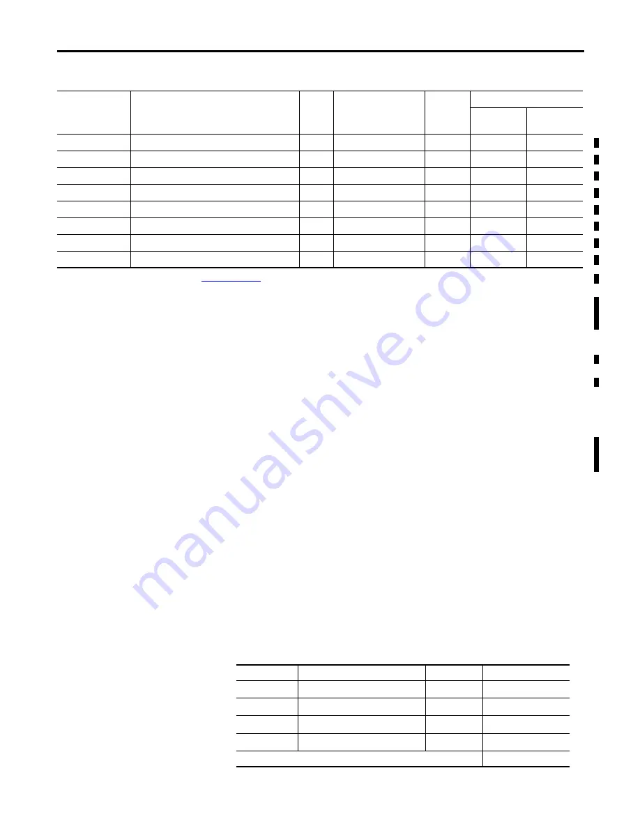
Table 12 - PFD Calculations - 5-year for ControlLogix Component
Cat. No.
(1)
(2)
Description
61508
(2010)
Mean Time Between
Failure (MTBF)
(9)
λ
(10)
Calculated PFD:
1oo1
Architecture
1oo2
Architecture
Table 13 - Example of PFD Calculations for a Fail-safe System
Cat. No.
Description
MTBF
Calculated PFD
1756-A
XX
ControlLogix chassis
22,652,009
9.6901E-06
1756-L61
ControlLogix 2 MB controller
1,000,053
2.1949E-04
1756-OB16D
DC output module
8,884,374
1.39367-07
1756-IB16D
DC diagnostic input module
30,228,640
1.39206E-07
Total PFD calculation for a safety loop consisting of these products:
Содержание 1756-L6 Series
Страница 24: ...24 Rockwell Automation Publication 1756 RM001I EN P May 2012 Chapter 1 SIL Policy Notes ...
Страница 60: ...60 Rockwell Automation Publication 1756 RM001I EN P May 2012 Chapter 5 ControlLogix I O Modules Notes ...
Страница 76: ...76 Rockwell Automation Publication 1756 RM001I EN P May 2012 Chapter 6 FLEX I O Modules Notes ...
Страница 120: ...120 Rockwell Automation Publication 1756 RM001I EN P May 2012 Appendix C PFD Calculations for a SIL 2 System Notes ...
Страница 126: ...126 Rockwell Automation Publication 1756 RM001I EN P May 2012 Appendix D Checklists Notes ...
Страница 133: ...Allen Bradley Motors ...