


Publication 1746-10.2– October 1997
(Catalog Number 1746-INT4)
Use this abbreviated procedure for getting the 1746-INT4 module into operation.
If you need more information, refer to the user manual, publication 1746-6.16.
1.
Unpack the Module
Reference
Important:: Follow these precautions to prevent damaging the module from electrostatic discharge:
•
Before handling the module, rid yourself of electric charge by touching a grounded object
•
Avoid touching connector terminations and circuit components.
•
When not in use, keep the module in its electrostatic shielded bag.
Unpack the module making sure that the contents include:
•
module (Catalog Number 1746-INT4)
•
removable terminal block (factory–installed on module) with CJC sensors attached
•
this Quick Start publication (1746-10.2)
–
If the contents are incomplete, call your local Allen-Bradley representative for assistance.
2.
Review Power Requirements
Reference
Review the power requirements of the modules drawing power from the chassis power supply.
•
The fixed, 2-slot chassis supports 2 1746-INT4 modules. If combining an INT4 module with
a different type of module, refer to Considerations for a Fixed Controller in chapter 3.
•
For a modular system, compute the total load on the system power supply using the proce-
dure described in the SLC Installation & Operation Manual for Modular Controllers (publica-
tion 1747-6.2) or the SLC 500 Family System Overview (publication 1747-2.30).
Chapter 3
(Installation and
Wiring)
Appendix A
(Specifications)
3.
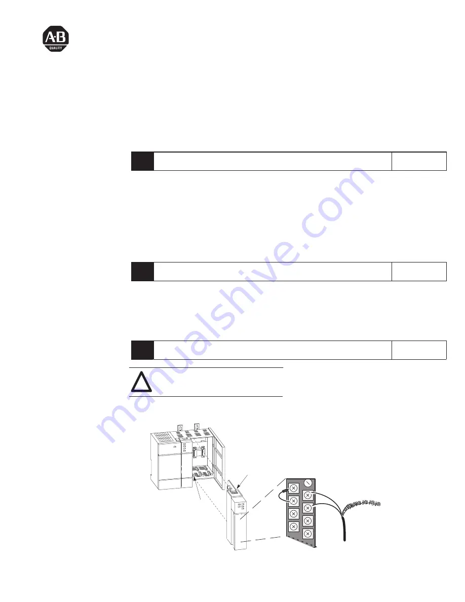
Install the Module and Connect the Thermocouples
Reference
ATTENTION: Never install, remove, or wire
modules with power applied to the chassis or
devices wired to the module.
!
Chapter 3
(Installation and
Wiring)
Insert/remove the module into/from the I/O chassis
(slot 1 in this example procedure).
card
guide
module release,
top and bottom
Connect thermocouple wires to channels 0-3.
We show an example for channel 0. Make sure
both cold junction compensation (CJC) devices
are securely attached with correct polarity.
CHL 0–
CJC A
Device
CHL 0+
Thermocouple Wire
Terminal Block
CHL 1+
CHL 1–
Important:
Ground all thermocouple shields
to earth ground at I/O chassis
with 3/8” braid wire. See User
Manual, figure 3.2.
+
–
Important:
Thermocouple inputs are highly
susceptible to electrical noise.
To minimize interference:
– Place processor and I/O chassis
in an industrial enclosure.
– Keep signal wires as far from
power and load lines as possible.
– Use shielded, twisted-pair
thermocouple extension wire.
– Ground each shield only at one end.
– Use correct thermocouple polarity.
– Keep all unshielded leads short.
– Connect the terminal block GND
(#18) to nearest I/O chassis mtg.
bolt with 12 gauge stranded wire.
Quick Start
Allen-Bradley Drives


