


112
Rockwell Automation Publication 1444-UM001D-EN-P - June 2018
Chapter 3
Configure the 1444 Dynamic Measurement Module
Table 19 - Hardware Configuration
Parameter
Values
Comment
Name
0…32 characters*
Name must start with a letter or underscore (“_”). All other characters can
be letters, numbers, or underscores. Name cannot contain two contiguous
underscore characters and cannot end in an underscore.
The module does not use Transducer Name but retains it for reference by
higher-level systems.
*If the channel name is used to create and name a measurement Location
in Emonitor®, then note that the Emonitor Location name is limited to 16
characters.
If the channel name is greater than 16 characters, the TRAILING 16
characters are used by the Emonitor Extraction Manager (EEM) utility to
create data locations in the Emonitor database for 1444 Series monitor
data.
Measurement
Type
See following table. Also see
.
Measurement Type selections are intended to simplify configuration of
various common applications. It defines what filtering is applied (LP/HP),
the quality of the filtering (roll off), and if the measurement is integrated
or double integrated.
Displays the engineering units that results from applying the
Measurement Type (function) to the selected Transducer Units. This
engineering unit is associated with dynamic measures that are read from
the Post Filter signal source (see
).
Measurement
Units
—
Displays the engineering units that results from applying the
Measurement Type (function) to the selected Transducer Units. This
engineering unit is associated with dynamic measures that are read from
the Post Filter signal source (see
).
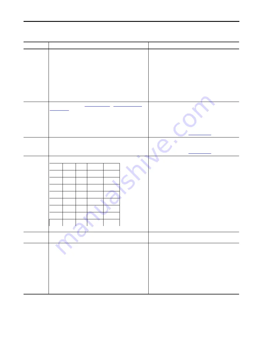
Xdcr Units
The supported engineering units include the following.
The Engineering Units cannot be set or changed if the Channel Type is OFF or gSE.
Select the Engineering Units the sensor measures and to which the
transducer sensitivity is referenced (in mV/Engineering Unit).
The Channel Type (Module Definition) and the Measurement Type
determine the available selections.
Xdcr Sensitivity
Any real number between 1 and 20,000.
Enter the sensitivity of the connected sensor in mV/Engineering Unit (EU
as specified in Xdcr Units in the preceding table).
Xdcr Power
Select from the following.
• Off
• +24V DC, 4 mA
• +24V DC, 25 mA
• -24V DC, 25 mA
Select the power option appropriate for the connected sensor.
• Select OFF for any self-powered sensor, or for sensors that are powered
from another source (including a barrier).
• +24V DC, 4 mA: This is a constant current (CC) source. It is required for
standard IEPE (ICP) accelerometers and other sensors that require a 4
mA CC source.
• +24V DC, 25 mA: This is a regulated positive voltage source. Many
position measurement sensors such as LVDTs and some vibration
sensors require a +24V supply.
• -24V DC, 25 mA: This is a regulated negative voltage source. It is
suitable for all API-670 compliant eddy current probes and other
sensors that require a -24V supply.
V
inch/s
bar
kW
UK g/min
mV
m/s
2
mbar
MW
m
3
/min
m
mm/s
2
psi
VA
gSE
mm
inch/s
2
A
kVA
RPM
micron
g
mA
VAR
RPM/min
inch
mg
K
kVAR
EU
mil
Pa
o
C
l/min
m/s
kPa
o
F
cfm
mm/s
MPa
W
US g/min
Содержание 1444-AOFX00-04RB
Страница 10: ...10 Rockwell Automation Publication 1444 UM001D EN P June 2018 Table of Contents Notes...
Страница 12: ...12 Rockwell Automation Publication 1444 UM001D EN P June 2018 Preface Notes...
Страница 198: ...198 Rockwell Automation Publication 1444 UM001D EN P June 2018 Chapter 5 Configure the Tachometer Expansion Module Notes...
Страница 210: ...210 Rockwell Automation Publication 1444 UM001D EN P June 2018 Chapter 7 Configure Relays Notes...
Страница 230: ...230 Rockwell Automation Publication 1444 UM001D EN P June 2018 Chapter 8 Configure Alarms Notes...
Страница 240: ...240 Rockwell Automation Publication 1444 UM001D EN P June 2018 Chapter 9 Trend and Transient Capture Notes...
Страница 316: ...316 Rockwell Automation Publication 1444 UM001D EN P June 2018 Chapter 10 Operate the Module Notes...
Страница 549: ......