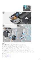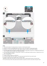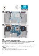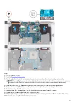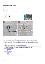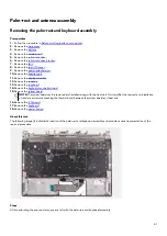
11. Remove the power-adapter port cable from the palm-rest and keyboard assembly and peel the power-adapter port cable off the
fan and heat-sink assembly.
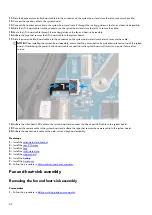
12. Peel the tape that secures the display cable to the system board.
13. Open the latch and disconnect the display cable from the system board and peel the display cable off the system board.
14. Remove the five screws (M2x4) that secure the system-board assembly to the palm-rest and keyboard assembly.
15. Grab the system-board assembly from the top left and right sides of the heat sink and lift the system-board assembly off the
palm-rest and keyboard assembly.
16. Place the system-board assembly on a clean and flat surface.
17. Turn the system-board assembly over.
18. Remove the
19. Turn the system-board assembly over.
20.After performing all the above steps, you are left with the system board.
CAUTION: Do not use alcohol wipes to clean the Element 31 thermal grease from the processor chip which is
surrounded by the processor barrier sheet. The alcohol solution from the wipes will dissolve the Element 31 thermal
grease into conductive metal particles. If these conductive metal particles come into contact with the surface of the
system board, it will cause the an electrical short when the computer is powered on.
NOTE: Before returning the faulty system board. Adhere the processor (CPU) sticker over the processor (CPU) chip and
ensure that it covers the entire surface of it.
Installing the system board
Prerequisites
If you are replacing a component, remove the existing component before performing the installation process.
About this task
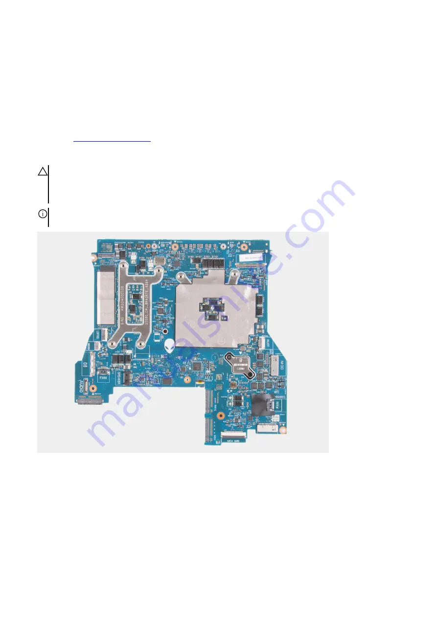
The following image indicates the connectors on your system board.
49
Содержание P111F
Страница 1: ...Alienware x15 R1 Service Manual Regulatory Model P111F Regulatory Type P111F001 May 2021 Rev A00...
Страница 8: ...4 Connect your computer and all attached devices to their electrical outlets 5 Turn on your computer 8...
Страница 13: ...13...
Страница 15: ...15...
Страница 28: ...28...

