background image

052

052

/

CHAPTER 10: PROCESSOR 

1

3

4

5

2

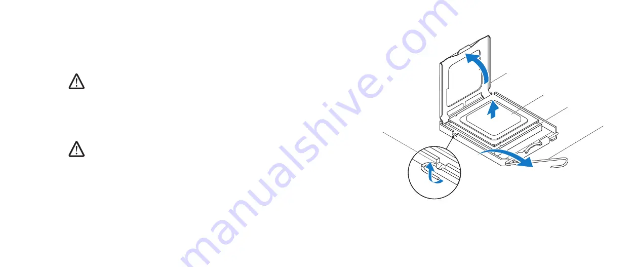
1 processor cover

2

processor

3 socket

4 release lever

5 tab

Removing the Processor


Follow the instructions in “Before You Begin” on page 

1. 

6.

Remove the left side-panel (see “Removing the Left Side-Panel“ on page 

2. 

11).

WARNING: Despite having a plastic shield, the processor liquid-cooling 

assembly may be very hot during normal operation. Ensure that it has 

had sufficient time to cool before you touch it.

Remove the processor liquid-cooling assembly (see “Removing the 

3. 

Processor Liquid-Cooling Assembly” on page 48).
Press and push the release lever down and out and release it from the tab 

4. 

that secures it.


CAUTION: When removing the processor, do not touch any of the pins 

inside the socket or allow any objects to fall on the pins in the socket.

Open the processor cover and gently lift the processor to remove it from the 

5. 

socket.
Leave the release lever extended in the release position so that the socket is 

6. 

ready for the new processor. 

Содержание AURORA D0IM

Страница 1: ...01 01 ALIENWARE AURORA SERVICE MANUAL...

Страница 2: ...marks of Microsoft Corporation in the United States and or other countries Intel and SpeedStep are registered trademarks of Intel Corporation in the U S and other countries Other trademarks and trade...

Страница 3: ...the Drive Bay Shroud 19 Replacing the Drive Bay Shroud 19 CHAPTER 5 DRIVE S 20 Removing the Hard Drive s 22 Replacing the Hard Drive s 24 Removing the Optical Drive s 25 Replacing the Optical Drive s...

Страница 4: ...8 FRONT BEZEL 88 Removing the Front Bezel 90 Replacing the Front Bezel 92 CHAPTER 9 PROCESSOR LIQUID COOLING ASSEMBLY 46 Removing the Processor Liquid Cooling Assembly 48 Replacing the Processor Liqui...

Страница 5: ...PTER 20 BLUETOOTH ASSEMBLY 98 Removing the Bluetooth Assembly 100 Replacing the Bluetooth Assembly 101 CHAPTER 21 TOP I O PANEL 102 Removing the Top I O Panel 104 Replacing the Top I O Panel 105 CHAPT...

Страница 6: ...lowing conditions exist You have performed the steps in Turning Off Your Computer on page 7 and Before Working Inside Your Computer on page 8 You have read the safety information that shipped with you...

Страница 7: ...ck Start click the arrow and then click Shut Down Windows 7 Click Start Shut Down The computer turns off after the operating system shutdown process 3 finishes Ensure that the computer is turned off I...

Страница 8: ...omputer on its side Before Working Inside Your Computer Use the following safety guidelines to help protect your computer from potential damage and to help to ensure your own personal safety WARNING B...

Страница 9: ...CHAPTER 2 LEFT SIDE PANEL 09 09 CHAPTER 2 LEFT SIDE PANEL CHAPTER 2 SIDE PANEL...

Страница 10: ...rd against likelihood of electric shock laceration by moving fan blades or other unexpected injuries always unplug your computer from the electrical outlet before removing the side panel s WARNING Do...

Страница 11: ...Slide the latch to unlock the release panel 2 Lift the release panel 3 Place the left side panel in a secure location 4 NOTE Theater lighting available only in Alienware Aurora ALX turns on automatica...

Страница 12: ...CHAPTER 3 TECHNICAL OVERVIEW 012 012 CHAPTER 3 TECHNICAL OVERVIEW CHAPTER 3 TECHNICAL OVERVIEW...

Страница 13: ...cal drives 3 4 hard drives 4 Inside View Of Your Computer WARNING Before working inside your computer read the safety information that shipped with your computer For additional safety best practices i...

Страница 14: ...nnector USB1 17 USB connector USB2 18 USB connector USB3 19 Low Pin Count Debug Header LPC1 20 1394 connector 1394 21 PCI Express x1 connector SLOT4 22 S PDIF connector SPDIF 23 front audio connector...

Страница 15: ...D board connector BLINK 12 wireless connector WIRELESS 13 hard drive LED connector HDD_LED1 14 hard drive LED connector HDD_LED2 15 USB connector MB_USB 16 main power connector PWR1 17 system board li...

Страница 16: ...CHAPTER 4 SHROUDS 016 016 CHAPTER 5 SHROUDS CHAPTER 4 SHROUDS...

Страница 17: ...ry_compliance WARNING Do not operate your computer with any cover s including computer covers bezels filler brackets front panel inserts etc removed WARNING To guard against electrical shock always un...

Страница 18: ...e button and rotate the PCI shroud away from the chassis 3 Closing the PCI Shroud Follow the instructions in Before You Begin on page 1 6 Lower the PCI shroud into the chassis until it clicks into pla...

Страница 19: ...tery cable from the connector on the 5 master I O board Replacing the Drive Bay Shroud Follow the instructions in Before You Begin on page 1 6 Connect the drive bay shroud battery cable to the connect...

Страница 20: ...CHAPTER 5 DRIVE S 020 020 CHAPTER 6 DRIVE S CHAPTER 5 DRIVE S...

Страница 21: ...ician should perform repairs on your computer Damage due to servicing that is not authorized by Dell is not covered by your warranty CAUTION To prevent data loss turn off your computer see Turning Off...

Страница 22: ...a you want to keep back up your files before you begin this procedure Follow the instructions in Before You Begin on page 1 6 Remove the left side panel see Removing the Left Side Panel on page 2 11 D...

Страница 23: ...the hard drive assembly out of the hard 4 drive cage 1 2 1 hard drive assembly 2 release tabs 2 5 Remove the hard drive out of the hard drive bracket by releasing the tabs and lifting the hard drive...

Страница 24: ...is correct Snap the hard drive bracket on to the new hard drive if applicable 3 Slide the hard drive assembly into the hard drive cage until the release tabs 4 snap into place Connect the power and d...

Страница 25: ...Press the AlienHead on the front of your computer to lower the drive panel 2 Remove the left side panel see Removing the Left Side Panel on page 3 11 Open the PCI shroud see Opening the PCI Shroud on...

Страница 26: ...cable 3 Lift the securing tab and slide the optical drive through the front of the 4 computer until the securing tabs snap into place Connect the power and data cables to the optical drive if applicab...

Страница 27: ...s the AlienHead on the front of your computer to lower the drive panel 2 Remove the left side panel see Removing the Left Side Panel on page 3 11 Open the PCI shroud see Opening the PCI Shroud on page...

Страница 28: ...028 028 CHAPTER 5 DRIVE S 1 2 1 Media Card Reader 2 screws 4 Remove the four screws that secure the Media Card Reader to the FlexBay 7 dock Slide the Media Card Reader out of the FlexBay dock 8...

Страница 29: ...secure the Media Card Reader to the FlexBay 4 dock Lift the securing tab and slide the FlexBay dock through the front of the 5 computer until the securing tabs snap into place Connect the FlexBay USB...

Страница 30: ...CHAPTER 6 PCI EXPRESS CARD S 030 030 CHAPTER 6 PCI EXPRESS CARD S CHAPTER 6 PCI EXPRESS CARD S...

Страница 31: ...om regulatory_compliance WARNING Do not operate your computer with any cover s including computer covers bezels filler brackets front panel inserts etc removed WARNING To guard against electrical shoc...

Страница 32: ...the system board see System Board 4 Components on page 14 Disconnect any cables connected to the card if applicable 5 Remove the screw that secures the card to the chassis 6 Remove the card 7 For a P...

Страница 33: ...ER 6 PCI EXPRESS CARD S 1 2 1 filler bracket 2 screw Replacing the PCI Express Card s Follow the instructions in Before You Begin on page 1 6 Remove the filler bracket to create a card slot opening if...

Страница 34: ...slot If you are installing the PCI Express x16 card push the retention mechanism and insert the card in the connector Connect any cables that should be attached to the card if applicable 5 For informa...

Страница 35: ...pecifications at support dell com manuals for information on the type of memory supported by your computer Install only memory modules that are supported by your computer NOTE Memory modules purchased...

Страница 36: ...regulatory_compliance WARNING Do not operate your computer with any cover s including computer covers bezels filler brackets front panel inserts etc removed WARNING To guard against electrical shock a...

Страница 37: ...ation Allow the memory module s to cool before touching them NOTE For better access to the memory module s remove the graphics card if the card is full length To remove the graphics card see Removing...

Страница 38: ...h 4 securing clips 2 5 memory module Replacing the Memory Module s Recommended memory configuration slots 1 3 and 5 or slots 1 6 1 Follow the instructions in Before You Begin on page 6 Align the notch...

Страница 39: ...y module is not installed properly the computer may not boot To replace the graphics card see Replacing the PCI Express Card s on 4 page 33 Replace the left side panel see Replacing the Left Side Pane...

Страница 40: ...CHAPTER 8 FANS 040 040 CHAPTER 8 FANS CHAPTER 8 FANS...

Страница 41: ...compliance WARNING To guard against electrical shock always unplug your computer from the electrical outlet before removing the side panel s WARNING Do not operate your computer with any cover s inclu...

Страница 42: ...de panel see Removing the Left Side Panel on page 2 11 Open the PCI shroud see Opening the PCI Shroud on page 3 18 Remove the drive bay shroud see Removing the Drive Bay Shroud on 4 page 19 Disconnect...

Страница 43: ...the slot in the hard drive bay 3 Connect the hard drive fan assembly cable to the connector on the master 4 I O board Replace the drive bay shroud see Replacing the Drive Bay Shroud on 5 page 19 Clos...

Страница 44: ...he Left Side Panel on page 2 11 Open the PCI shroud see Opening the PCI Shroud on page 3 18 Remove the drive bay shroud see Removing the Drive Bay Shroud on 4 page 19 Remove full length PCI Express ca...

Страница 45: ...ssembly cable to the connector on the master 4 I O board Replace full length PCI Express cards if any see Replacing the PCI Express 5 Card s on page 33 Replace the drive bay shroud see Replacing the D...

Страница 46: ...CHAPTER 9 PROCESSOR LIQUID COOLING ASSEMBLY 046 046 CHAPTER 9 PROCESSOR LIQUID COOLING ASSEMBLY CHAPTER 9 LIQUID COOLING ASSEMBLY...

Страница 47: ...your computer from the electrical outlet before removing the side panel s WARNING Do not operate your computer with any cover s including computer covers bezels filler brackets front panel inserts etc...

Страница 48: ...ving a plastic shield the processor liquid cooling assembly may be very hot during normal operation Ensure that it has had sufficient time to cool before you touch it Disconnect the processor liquid c...

Страница 49: ...place the four screws that secure the processor liquid cooling assembly 3 to the chassis rear wall Tighten the four captive screws that secure the processor liquid cooling 4 assembly to the system boa...

Страница 50: ...CHAPTER 10 PROCESSOR 050 050 CHAPTER 9 PROCESSOR CHAPTER 10 PROCESSOR...

Страница 51: ...uard against electrical shock always unplug your computer from the electrical outlet before removing the side panel s CAUTION Only a certified service technician should perform repairs on your compute...

Страница 52: ...has had sufficient time to cool before you touch it Remove the processor liquid cooling assembly see Removing the 3 Processor Liquid Cooling Assembly on page 48 Press and push the release lever down a...

Страница 53: ...w processor do not to touch the underside of the processor 2 CAUTION You must position the processor correctly in the socket to avoid permanent damage to the processor and the computer when you turn o...

Страница 54: ...e processor is fully seated in the socket close the processor cover 6 Ensure that the tab on the processor cover is positioned underneath the center cover latch on the socket Pivot the socket release...

Страница 55: ...CHAPTER 11 POWER SUPPLY 055 055 CHAPTER 10 POWER SUPPLY CHAPTER 11 POWER SUPPLY...

Страница 56: ...gulatory_compliance WARNING To guard against electrical shock always unplug your computer from the electrical outlet before removing the side panel s WARNING Do not operate your computer with any cove...

Страница 57: ...ctions in Before You Begin on page 1 6 Remove the left side panel see Removing the Left Side Panel on page 2 11 Lift the tab and slide the power supply cover towards the back of the 3 chassis Lift the...

Страница 58: ...screws that secure the power supply to the back of 6 the chassis Slide the power supply through the back of the chassis 7 1 2 1 power supply 2 captive screws 4 Remove the four screws that secure the...

Страница 59: ...uter 3 Tighten the four captive screws that secure the power supply to the back of 4 the chassis Connect the AC power cable to the power supply 5 Align the tabs on the power supply cover with the slot...

Страница 60: ...CHAPTER 12 BATTERY 060 060 CHAPTER 14 COIN CELL BATTERY CHAPTER 12 BATTERY...

Страница 61: ...ory_compliance WARNING Do not operate your computer with any cover s including computer covers bezels filler brackets front panel inserts etc removed WARNING To guard against electrical shock always u...

Страница 62: ...Opening the PCI Shroud on page 4 18 Remove any PCI Express cards see Removing the PCI Express Card s on 5 page 32 Locate the battery socket see System Board Components on page 6 14 CAUTION If you pry...

Страница 63: ...battery Replacing the Coin Cell Battery Follow the instructions in Before You Begin on page 1 6 Insert the new battery CR2032 into the socket with the side labeled 2 facing up and press the battery in...

Страница 64: ...1 6 Remove the left side panel see Removing the Left Side Panel on page 2 11 Open the PCI shroud see Opening the PCI Shroud on page 3 18 Remove the drive bay shroud see Removing the Drive Bay Shroud o...

Страница 65: ...er lighting 2 battery compartment Close the theater lighting battery compartment door 3 Replace the drive bay shroud see Replacing the Drive Bay Shroud on 4 page 19 Close the PCI shroud see Closing th...

Страница 66: ...CHAPTER 13 SYSTEM BOARD 066 066 CHAPTER 11 SYSTEM BOARD CHAPTER 13 SYSTEM BOARD...

Страница 67: ...gulatory_compliance WARNING Do not operate your computer with any cover s including computer covers bezels filler brackets front panel inserts etc removed WARNING To guard against electrical shock alw...

Страница 68: ...ge 5 32 WARNING Despite having a plastic shield the processor liquid cooling assembly may be very hot during normal operation Ensure that it has had sufficient time to cool before you touch it Remove...

Страница 69: ...ge 6 53 Replace the processor liquid cooling assembly see Replacing Processor 7 Liquid Cooling Assembly on page 49 Replace the PCI Express cards see Replacing the PCI Express Card s on 8 page 33 Close...

Страница 70: ...CHAPTER 14 MASTER I O BOARD 070 070 CHAPTER 12 MASTER I O BOARD CHAPTER 14 MASTER I O BOARD...

Страница 71: ...rom the electrical outlet before removing the side panel s WARNING Do not operate your equipment with any cover s including side panels bezels filler brackets front panel inserts etc removed CAUTION O...

Страница 72: ...e bay shroud see Removing the Drive Bay Shroud on 4 page 19 Remove the PCI fan assembly see Removing the PCI Fan Assembly on 5 page 44 Disconnect all cables from the connectors on the master I O board...

Страница 73: ...connect the cables that you removed from the connectors on the 4 master I O board Replace the PCI fan assembly see Replacing the PCI Fan Assembly on 5 page 45 Replace the drive bay shroud see Replacin...

Страница 74: ...CHAPTER 15 TOP LIGHTING BOARD 074 074 CHAPTER 13 TOP LIGHTING BOARD CHAPTER 15 TOP LIGHTING BOARD...

Страница 75: ...com regulatory_compliance WARNING To guard against electrical shock always unplug your computer from the electrical outlet before removing the side panel s CAUTION Only a certified service technician...

Страница 76: ...ove the four screws that secure the top lighting board to the chassis 4 Pull the top lighting board away from the chassis 5 Replacing the Top Lighting Board Follow the instructions in Before You Begin...

Страница 77: ...CHAPTER 16 RIGHT SIDE PANEL S 077 077 CHAPTER 16 RIGHT SIDE PANEL S CHAPTER 16 RIGHT SIDE PANEL...

Страница 78: ...com regulatory_compliance WARNING Do not operate your computer with any cover s including computer covers bezels filler brackets front panel inserts etc removed WARNING To guard against electrical sho...

Страница 79: ...nel on page 2 11 Open the PCI shroud see Opening the PCI Shroud on page 3 18 Remove the drive bay shroud see Removing the Drive Bay Shroud on 4 page 19 Remove the power supply cover see Removing the P...

Страница 80: ...right top panel away from the chassis 9 1 1 right top panel Disconnect the lighting board cable from the connector on the master I O 10 board Remove the two screws that secure the lighting board to th...

Страница 81: ...ition 5 Replace the three screws that secure the right side panel s to the chassis 6 Replace the power supply cover see Replacing the Power Supply Cover on 7 page 59 Replace the hard drive fan assembl...

Страница 82: ...CHAPTER 17 ACTIVE VENTING ASSEMBLY 082 082 CHAPTER 17 ACTIVE VENTING ASSEMBLY CHAPTER 17 ACTIVE VENTING ASSEMBLY...

Страница 83: ...dell com regulatory_compliance WARNING Do not operate your computer with any cover s including computer covers bezels filler brackets front panel inserts etc removed WARNING To guard against electrica...

Страница 84: ...are Aurora ALX Follow the instructions in Before You Begin on page 1 6 Remove the left side panel see Removing the Left Side Panel on page 2 11 Open the PCI shroud see Opening the PCI Shroud on page 3...

Страница 85: ...ce the chassis upright 8 Remove the right top panel 9 1 1 right top panel Remove the top lighting board see Removing the Top Lighting Board on 6 page 76 Remove the ten screws that secure the active ve...

Страница 86: ...ews that secure the top panel to the chassis 10 Lift the top panel away from the chassis 11 Remove the three screws that secure the active venting assembly to the 12 chassis Disconnect the cables that...

Страница 87: ...ow the instructions in Before You Begin on page 1 6 Place the active venting assembly on the top of the chassis 2 Connect the cables that connect the active venting assembly to the 3 connectors on the...

Страница 88: ...CHAPTER 18 FRONT BEZEL 088 088 CHAPTER 18 FRONT BEZEL CHAPTER 18 FRONT BEZEL...

Страница 89: ...ulatory_compliance WARNING Do not operate your computer with any cover s including computer covers bezels filler brackets front panel inserts etc removed WARNING To guard against electrical shock alwa...

Страница 90: ...CI shroud see Opening the PCI Shroud on page 3 18 Remove the drive bay shroud see Removing the Drive Bay Shroud on 4 page 19 Remove the right side panel s see Removing the Right Side Panel s on 5 page...

Страница 91: ...APTER 18 FRONT BEZEL 1 2 1 screws 3 2 front bezel Place the chassis upright 8 Remove the three screws on the right side that secure the front bezel to the 9 chassis Pull the front bezel away from the...

Страница 92: ...bezel cables to the connector on the master I O board 5 Replace the seven screws that secure the front bezel to the chassis 6 Replace the right side panel s see Replacing the Right Side Panel s on 7...

Страница 93: ...CHAPTER 19 BACK BEZEL 093 093 CHAPTER 16 BACK PANEL CHAPTER 19 BACK BEZEL...

Страница 94: ...latory_compliance WARNING Do not operate your computer with any cover s including computer covers bezels filler brackets front panel inserts etc removed WARNING To guard against electrical shock alway...

Страница 95: ...side panel see Removing the Left Side Panel on page 2 11 Remove the power supply see Removing the Power Supply on page 3 57 Remove the processor liquid cooling assembly see Removing the 4 Processor L...

Страница 96: ...BACK BEZEL 3 1 2 1 screws 2 2 back bezel 3 tabs Remove the two screws that secure the back bezel to the chassis 7 Release the tabs that secure the back bezel to the chassis 8 Pull the back bezel away...

Страница 97: ...the back bezel to the chassis 4 Replace the two screws that secure the security lock panel to the chassis 5 Replace the processor liquid cooling assembly see Replacing the Processor 6 Liquid Cooling...

Страница 98: ...CHAPTER 20 BLUETOOTH ASSEMBLY 098 098 CHAPTER 18 FRONT BEZEL CHAPTER 20 BLUETOOTH ASSEMBLY...

Страница 99: ...com regulatory_compliance WARNING Do not operate your computer with any cover s including computer covers bezels filler brackets front panel inserts etc removed WARNING To guard against electrical sho...

Страница 100: ...ou Begin on page 1 6 Remove the left side panel see Removing the Left Side Panel on page 2 11 Open the PCI shroud see Opening the PCI Shroud on page 3 18 Remove the drive bay shroud see Removing the D...

Страница 101: ...rew that secures the Bluetooth assembly to the 3 chassis Connect the Bluetooth cable to the connector on the master I O board 4 Replace the drive bay shroud see Replacing the Drive Bay Shroud on 5 pag...

Страница 102: ...CHAPTER 21 TOP I O PANEL 0102 0102 CHAPTER 20 TOP I O CHAPTER 21 TOP I O PANEL...

Страница 103: ...regulatory_compliance WARNING Do not operate your computer with any cover s including computer covers bezels filler brackets front panel inserts etc removed WARNING To guard against electrical shock a...

Страница 104: ...assembly see Removing the PCI Fan Assembly on 5 page 44 Remove PCI Express cards see Removing the PCI Express Card s on 6 page 32 Remove the active venting assembly see Removing the Active Venting 7...

Страница 105: ...p I O Panel Follow the instructions in Before You Begin on page 1 6 Align and replace the top I O panel 2 Connect the cables that connect the top I O panel to the system board and 3 master I O board R...

Страница 106: ...CHAPTER 22 SYSTEM SETUP 0106 0106 CHAPTER 21 SYSTEM SETUP CHAPTER 22 SYSTEM SETUP...

Страница 107: ...rvals until the System Setup screen appears System Setup Screens The BIOS Setup Utility window displays current or changeable configuration information for your desktop Key functions appear at the bot...

Страница 108: ...puter System Setup Options NOTE The items listed in this section may or may not appear exactly as listed depending on your computer model and installed devices System Information Product Name Displays...

Страница 109: ...ed hard drive controller to AHCI or RAID AHCI CD DVD Boot Time out Allows you to set the wait time for SATA or CD DVD in AHCI mode Advanced BIOS Features NumLock Status Select power on state for num l...

Страница 110: ...tion submenu Overclock Configuration Allows you to access the Overclock Configuration submenu Overvoltage Configuration Allows you to access the Overvoltage Configuration submenu Load Level1 OC Settin...

Страница 111: ...than marked 1 4 Core CPU Turbo Ratio Limit Limit ratio for cores 1 4 XE processors only Advance DRAM Configuration Submenu Memory Z Opens submenu to display the SPD configuration for each memory modu...

Страница 112: ...guration Submenu Turbo Mode TDC Limit Override Program the current thresholds for the processor while in turbo mode Turbo Mode TDP Limit Override Program the power thresholds for the processor while i...

Страница 113: ...oving the Left Side Panel on page 2 11 Reset the current password and CMOS settings 3 Locate the 3 pin CMOS or password reset jumper on the system board a see System Board Components on page 14 Remove...

Страница 114: ...0114 0114 CHAPTER 22 SYSTEM SETUP PASSWORD Replace the left side panel see Replacing the Left Side Panel on page 4 11 Connect your computer and devices to electrical outlets and then turn 5 them on...

Страница 115: ...Download window appears Click 8 Save to save the file on your desktop The file downloads to your desktop Click 9 Close if the Download Complete window appears The file icon appears on your desktop and...

Отзывы: