background image

12 


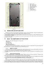
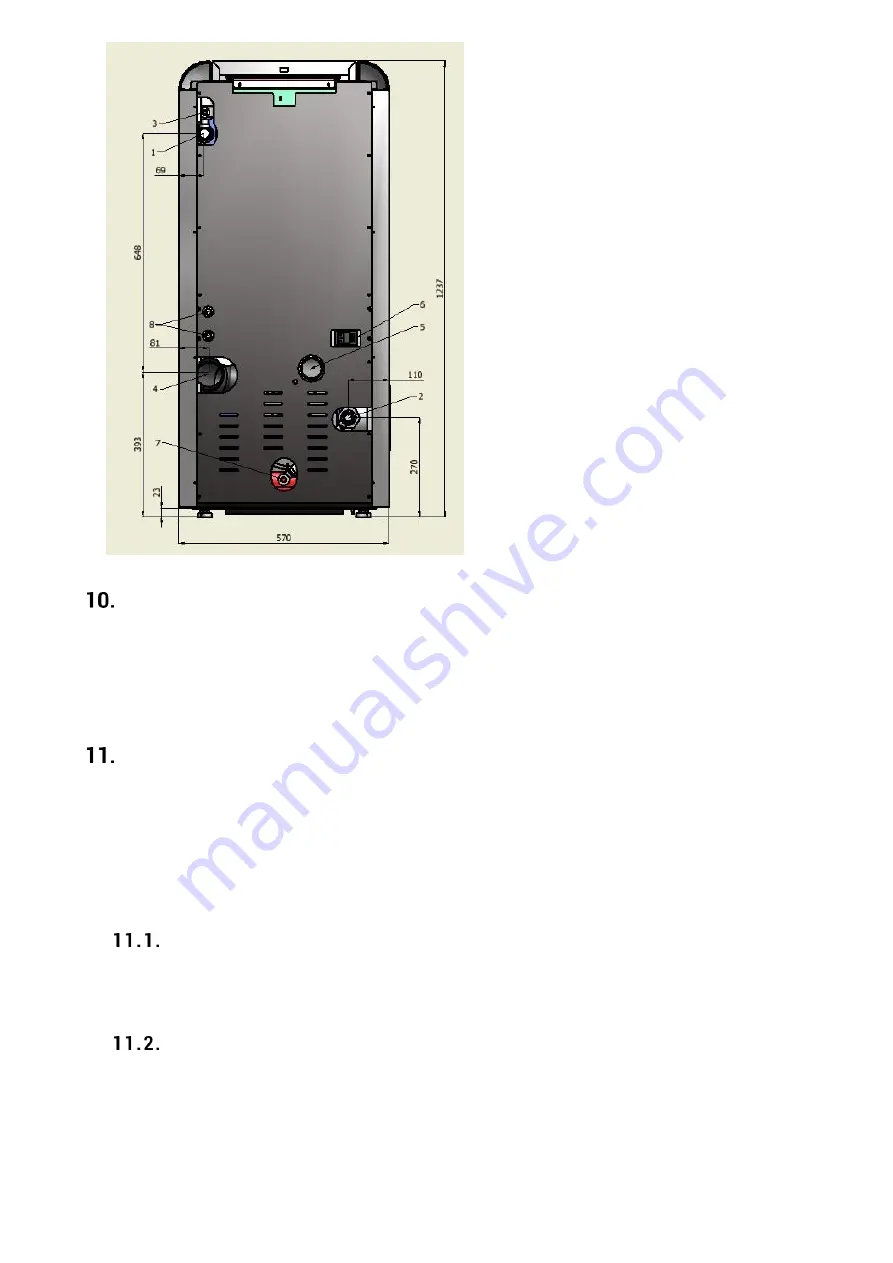
Figure 16 


PRESSURE AND RETURN PIPE  

 
Outputs of the pressure and return pipes on the boiler are 1'' and you cannot reduce them or taper to the first bifurcation. 

Use a 1’’ steel pipe or a copper pipe with the outside diameter of Ø28mm or greater. 

When installing, strictly observe the slopes of pipes as they need to be at 0.5% (5mm. per meter of pipe) and the venting 

system (boiler, pipes, radiators). 

Set up a thermo hydrometer at the pressure line to show the water pressure in the system and the water temperature at 

the back end of the boiler. 


BUILT-IN COMPONENT OF THE STOVE 

 
- In the stove, there are the following built-in components: 
- Safety valve 
- Circulation pump 
- Automatic air valve 
- Expansion container and 
- Charging and discharging tap 
For this reason there is no need to install these components again. The stove is complete, which is a great advantage most 

all of because there is no need for additional space for the listed components. 


SAFETY VALVE   

It is set up under the lid of the stove on the pressure line. Input connection is R1/2". It opens with water pressure of 2.5 bar.  

You can get to it by removing the right lateral side, when you are looking at the stove. 

The output safety valves whose connection protrudes through the rear wall above the pressure line should be put into the 

sewer pipes. 


CIRCULATION PUMP  

A high-quality Wilo RS 25/6 – circulation pump has been built into the stove on the return line of R1”. The power of the 

pump is 93W. It is turned on and off by the electronics by the set water temperature. 

The pump shaft has to be in a horizontal position. For this reasons, when connecting with the installation make sure that 

the pump does not turn around! Firmly hold galvanized bolt at the end of the back side. 

You can reach the pump by removing the left lateral side, when you are looking at the stove. 
Note: 
If the stove and the pump have been idle for a long time (a month, for example), the pipe shaft can stick to the base, it may 

not move the water, or it can burn out. If when starting the stove when the water in the boiler heats up the water pump does 
not start, if the radiators do not heat up when the set temperature is reached, if you do not hear the murmur of water (moving), 
or  if  the  boiler  temperature  rises  and  radiators  are  not  warming,  remove  the  left  lateral  side  as  indicated  in  the  previous 

1.


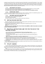
Wather outlet 1 

2.


Pipe of return wather 

3.


Pipe of safetly valve 

4.


Fume connectione 80 

5.


Primary air pupe 

6.


Main switch 

7.


Draining valve ½’’ 

8.


Security thermostats 

Содержание DINO 27

Страница 1: ...uel from timber biomass biofuels INSTRUCTIONS FOR CONNECTING OPERATION AND MAINTENANCE OF THE STOVE This product meets the requirements of the Ecodesign Directive in terms of efficiency and air pollut...

Страница 2: ...bustion of the pellet in the stove emits the same amount of carbon dioxide CO2 which would be freed as a result of the natural decay of wood The amount of carbon dioxide CO2 obtained through combustio...

Страница 3: ...g h 11 Degree of efficiency at maximum power 93 5 12 Minimum stove power radiation of water included 8 4 kW 13 Radiation stove power at minimum power 1 kW 14 The power of a water heater at minimum pow...

Страница 4: ...NG AND MAINTENANCE for employees who do maintenance 10 SPECIAL MAINTENANCE 10 IMPORTANT SAFETY INFORMATION 10 THE PELLET QUALITY IS VERY IMPORTANT 11 STORING THE PELLET 11 CONNECTING THE HYDRAULIC INS...

Страница 5: ...rd This is because the brunt of the stove is forward During transportation of the stove which has to be completely safe make sure that the forklift has the load that is greater than the weight of the...

Страница 6: ...wood e g beams or other combustible material located near the stove should be protected covered with fireproof material Leave enough clearance for maintenance work If the stove is installed in a kitc...

Страница 7: ...o 15 x 15 cm or a diameter of up to 15 cm and if there is a cover for checking and cleaning If the chimney has a larger cross section than 15x15cm or a diameter greater than 15cm a possible increased...

Страница 8: ...r cleaning the ashes is completely sealed and to seal it after each cleaning Please make sure everything is properly returned to its place and check the condition of the seals Figure 2a Cleaning eleme...

Страница 9: ...id for cleaning plug in SMER DIMA NE DA Figure 7 Mounting the flue pipe Insulation thickness mm Diameter of the smoke exhaust pipe mm D 80 D 100 Diameters of the holes holes to be made mm The walls ar...

Страница 10: ...This hole must be made on the outer wall of the room where the stove is located The supply of combustion air from the garage a warehouse for combustible materials or from a room where there are risks...

Страница 11: ...uld be cold and that the ashes should be cold as well They need to make sure the handles are cold as well NEVER TURN THE STOVE ON if there is just one of the safety devices that is defective improperl...

Страница 12: ...sive cleaners for cleaning the surface of the stove ROUTINE CLEANING AND MAINTENANCE DONE BY THE USER OF THE STOVE Use a drum shaped vacuum cleaner that can facilitate cleaning the stove The vacuum cl...

Страница 13: ...pulling the mechanism button a few times back and forth you will clean the chamber Do not worry if the mechanism moves slowly if it scratches or gets caught This is how it cleans the chamber Clean th...

Страница 14: ...er burning two tons of pellets Make sure the stove and the ash are cool The smoke channel chimney is resistant to wind and has to be checked and cleaned every year best at the beginning of the heating...

Страница 15: ...poor performance of the stove in case of use of the pellets of inappropriate quality STORING THE PELLET The pellets must be kept in a dry place that is not very cold Cold and moist pellets at the temp...

Страница 16: ...e looking at the stove The output safety valves whose connection protrudes through the rear wall above the pressure line should be put into the sewer pipes CIRCULATION PUMP A high quality Wilo RS 25 6...

Страница 17: ...out water It must be tied to the installation to which the consumers are connected radiators with minimum power of 8 kW PRACTICAL INSTRUCTIONS AND TIPS FOR THE USE OF THE HEATING SYSTEM All connection...

Страница 18: ...etting up and use simple and direct user functions reliable and flexible functional software specially developed for pellets burning appliances advanced features available to installers for adapting s...

Страница 19: ...oes into Standby mode LED symbols Igniter LED is on Igniter is on Auger LED is on Auger is active Pump LED is on Pump is active L3 Aux 1 output LED is on Aux 1 output is activated L4 Additional engine...

Страница 20: ...till in the ignition stage The system will stop working only when it enters the Run Mode Link Error This message informs you that there is no communication between the LCD display and the controller o...

Страница 21: ...buffer and other heating parameters Chrono Menu for selecting chrono program mode and boiler on off times Manual Load Menu for manual loading of the auger It is only feasible when the system is in the...

Страница 22: ...alues of the fan speed of the flue gas fans will be increased by 15 compared to the factory values Factory settings U03 1000 U04 1200 U05 1400 U06 1600 U07 1800 U11 900 Calibrated values U03 1150 U04...

Страница 23: ...e stove is set for precisely determined periods of time It contains two submenus Modality Programming Modality By entering the Chrono menu two submenus appear namely Modalities and Programming Via P4...

Страница 24: ...s that can be chosen Daily program the week day is selected and the system on and off times are programmed There are three time ranges for each day Weekly program system on off times are programmed fo...

Страница 25: ...n 3 seconds After that you can find the following functional conditions of the stove Check Up In the check up stage the initial check of the input signals of the stove and the correctness of the probe...

Страница 26: ...set water temperature it goes into modulation and continues to increase the water temperature by inertia up to the value 4 C higher than the set water temperature in the boiler 2 When an external roo...

Страница 27: ...for more than 3 seconds Contact a service Flue gas fan works at speed different than set Er11 Clock error Problems with internal clock Press and hold the P2 button for more than 3 seconds Check the ac...

Страница 28: ...itch on the back side of the stove and on the control panel the motherboard FLUE GASES FAN If the fan stops the motherboard immediately blocks the supply of pellets and an alarm signal will show GEAR...

Страница 29: ...throwing away or disposing of an old used stove is the sole responsibility of the owner The owner of the stove must abide by the regulations in his her country related to the safety and environment p...

Страница 30: ...was due to too much or too low voltage as well as due to force majeure Malfunctions of the appliance can be removed outside the warranty period with original spare parts that we also give a warranty f...

Отзывы: