background image

20 


When the water temperature approaches the stop temperature of 80ºC, the sensor starts the cooker to perform a series of 

cooling cycles or interrupts the operation of the cooker automatically by means of “ECO-STOP” to prevent the blocking of the 
capillary temperature sensor described above. 

- ELECTRICAL SAFETY 
The cooker is protected against high current interferences by standard fuses located in the main switch on the back of the 

cooker and on the control panel. 

- FLUE GAS FAN 
If the fan stops, the control panel is immediately blocking the pellets feed and the alarm signal is displayed.                                                                                      
- MOTOR WITH REDUCER 
When the engine with the gearbox stops working, the cooker continues to operate until the flame goes out due to the lack of 

oxygen and until the minimum cooling level is reached. 

- TEMPORARY POWER OUTAGE 
After a short power outage, the cooker automatically switches to cooling. 
- NO IGNITION 
When the flame does not develop during ignition stage, the cooker switches to alarm state. 


16.


FAULTS - CAUSES - SOLUTIONS 


PROBLEMS 

POSSIBLE CAUSES 

SOLUTIONS 

Pellets not 

inserted into the 
firebox. 

1. The pellets storage is empty. 
2. The infinite spiral is blocked. 
3. The reducer of the infinite spiral is 

defective. 

4. The electronic card is defective. 


1. Refill the storage 
2. Empty the storage and unblock the spiral - auger 
3. Replace the reducer 
4. Replace the electronic card 

The fire 

extinguishes or the 
cooker automatically 
turns off. 


1. The pellets storage is empty. 
2. The combustion chamber is not 

supplied with pellets. 

3. Pellets temperature probe 

intervention. 

4. Doors are not completely closed or 

gaskets are worn out. 

5. Inadequate pellets. 
6. Poor supply of pellets. 
7. The combustion chamber is dirty. 
8. The chimney is blocked. 
9. Interference or malfunction on the 

pressure switch.  

10. The engine of the smoke aspirator 

is damaged. 

1. Fill the storage with pellets. 
2. See the previous solution. 
3. Allow the cooker to cool down completely and 

turn it on again. If the problem persists, contact the 
technical service. 

4. Close the door or replace the gaskets with the 

genuine gaskets. 

5. Change the pellet type and select the type that is 

approved by the manufacturer. 

6. Check dosing and adjustment. 
7. Clean the combustion chamber according to the 

instructions in the manual. 

8. Allow the smoke duct to be cleaned. 
9. Replace the pressure switch. 
10. Check the engine and possibly replace it. 

The cooker works 

for a few minutes and 
then goes out. 

1. Ignition stage did not end. 
2. Temporary power outage. 
3. Flue duct clogged. 
4. Interference or fault in the 

temperature probe. 

5. Spark plug is damaged. 

1. Repeat the ignition stage. 
2. See the previous instruction. 
3. Clean the flue duct. 
4. Check or replace the probe. 
5. Check or replace the spark plug. 

Pellets are 

deposited in the 
combustion chamber. 
The door glass is dirty 
and the flame is weak. 

1. Lack of combustion air. 
2. Moist or inadequate pellets. 
3. Engine of the flue suction system is 

defective. 


1. Clean the combustion chamber and ensure that 

all openings are passable. Perform the standard 
cleaning of the combustion chamber and flue duct. 
Make sure the air supply is not blocked. Check the 
condition of the gaskets on the door.  

2. Change the type of pellets. 
3. Check the engine and possibly replace it. 

The engine of the 

vacuum cleaner does 
not work. 


1. Cooker does not receive electricity. 
2. Engine is damaged. 
3. Control panel is defective. 
4. Control panel does not work. 
 

1. Check the power supply network and the melting 

resistance safety. 

2. Check the engine and condenser and possibly 

replace. 

3. Replace the electronic card. 
4. Replace the control panel. 

In automatic 

mode, the cooker is 
constantly running at 
maximum capacity 


1. Thermostat is programmed to the 

maximum position 

2. Ambient air thermostat always 

measures cold air. 

3. Probe that measures the 

temperature is damaged. 

4. Control panel is faulty or not 

working. 

1. Set the temperature of the thermostat again. 
2. Change the position of the probe.  
3. Check the probe and possibly replace it. 
4. Check the control panel and possibly replace it. 

Cooker does not 

1. Lack of electricity 

1. Make sure the plug is pressed and the main 

Содержание ALFA TERM 20 PELET

Страница 1: ...SERBIA 1 Radni ka Street Tel 017 421 121 USER INSTRUCTIONS CENTRAL HEATING PELLET BURNING COOKER ALFA TERM 20 PELET Pellets wood biomass fuel biofuel COOKER INSTALLATION USE AND MAINTENANCE INSTRUCTIO...

Страница 2: ...0 Water content in the boiler 35 litara 31 Maximum operating pressure 2bar Dear buyer We thank you for choosing and buying our appliance in which we have invested a great effort so you could be satisf...

Страница 3: ...8 IMPORTANT SAFETY INFORMATION 5 9 CHOOSING PELLETS 6 9 1 PELLETS STORAGE 6 10 CONNECTING HYDRAULIC INSTALLATION 6 10 1 PRESSURE AND RETURN LINE 7 10 2 COOKER EMBEDDED COMPONENTS 7 10 3 SAFETY VALVE...

Страница 4: ...the technical level of knowledge at the moment of introduction of the cooker to the market ALFA PLAM will not consider other cookers that are already present on the market with the appropriate techni...

Страница 5: ...n serial number and CE marking 1 11 DELIVERY OF THE COOKER The cooker is delivered in wooden packaging It is attached to the wooden stand which provides its stability when moved with forklift and or o...

Страница 6: ...se personal protective equipment and other protective equipment Before starting any kind of maintenance make sure that the cooker if already used is cooled down DO NOT TURN THE COOKER ON even if only...

Страница 7: ...r combustion 5 Safety valve 6 Water pressure sensor 7 Air bleed vent 8 Lever of the flue pipes cleaning mechanism 9 Special key 10 Dashboard 11 Safety thermostat T 80 C 12 Switch 13 Safety thermostat...

Страница 8: ...s The cooker must be set up on the floor of the appropriate load capacity Cooker assembly and disassembly instructions are exclusively intended for authorized installers The installer must prior to co...

Страница 9: ...e is 4 5 m with a maximum of 3 knees at 90 The air inlet hole must be set at a height of about 20 30 cm from the ground One grid for continuous ventilation must be installed outside In very windy area...

Страница 10: ...conditions of poor airflow the presence of many curves inadequate ending of the outlet etc the extraction of smoke might be inappropriate In this case it will be necessary to change the operating para...

Страница 11: ...ntake opening is positioned so it cannot be accidentally blocked In the event that it is impossible to achieve external air intake through the wall behind the cooker the wall is not outer an opening m...

Страница 12: ...form any type of modification for whatever reason other than those allowed and recommended by the manufacturer itself Always use genuine spare parts Never wait for the components to wear out before re...

Страница 13: ...lar cleaning and maintenance is a prerequisite for the proper and efficient operation of the cooker IMPORTANT Clean the appliance only when the cooker and ashes are cold Using the ash vacuum cleaner c...

Страница 14: ...ray fasteners and turn the lock handle 90 in the clockwise direction Figure 14 The cooker must be cleaned regularly in order to function properly and fully use the power and save fuel Locations indica...

Страница 15: ...y to check and remove any ash and soot layer before closing the smoke passage It is best to contact an authorized professional chimney sweeper to clean the chimney If the chimney is not cleaned the fo...

Страница 16: ...oken pellets are fed into the fuel storage it can block the pellet injection Such a pellet can lead to burnout of the electric motor that drives the pellet insertion mechanism or to damage on gear uni...

Страница 17: ...and off by the electronics according to the set water temperature The pump axis must be in the horizontal position When connecting with the installation make sure the pump does not turn over Note If...

Страница 18: ...tion should be tested with water at a maximum pressure of 1 9 bar It is desirable to drain the water out of the system at least once due to the dirt that is in the system Make sure all valves between...

Страница 19: ...f the cooker and maximum functional utilization of the cooker It is characterized by simplicity of setting up and use simple and direct user functions reliable and flexible functional software special...

Страница 20: ...ing the button for more than 3 seconds the system goes into Standby mode LED symbols Igniter LED is on Igniter is on Auger LED is on Auger is active Pump LED is on Pump is active L3 Aux 1 output LED i...

Страница 21: ...f the cooker is necessary Block Ignition This message appears when the system turns off while it is still in the ignition stage The system will stop working only when it enters the Run Mode Link Error...

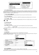
Страница 22: ...played Menu Description Combustion Management Menu for modification of combustion power calibration of work gear engine and flue gas engine Heating Management Menu for modification the setpoints for t...

Страница 23: ...5 10 means that the calibrated values of the auger speed will be reduced by 10 compared to the factory values Factory settings C03 60 0 C04 90 0 C05 120 0 C06 160 0 C07 200 0 C11 600 Calibrated value...

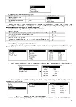
Страница 24: ...tive 14 3 2 6 REMOTE KEYBOARD This menu allows control via radio room thermostat It must be activated by pre setting a specific parameter 14 3 3 CHRONO MENU In this menu the system on off times are se...

Страница 25: ...elect the time period for turning on off P4 or P6 Entering the change mode selected time flashes P3 Change of time P4 or P6 Saving the change in the program P3 Turning on the program appears or turnin...

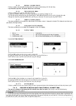
Страница 26: ...tness on the LCD displeja 14 3 9 1 SETTING CONTRAST Via P4 and P6 buttons contrast is increased or decreased By pressing the P3 button the changes are saved and one can exit the menu Via P1 button one...

Страница 27: ...active Run Mode After the stabilization stage the cooker operation stage starts At this stage there are five power levels that can be adjusted At this stage the igniter is switched off while the auge...

Страница 28: ...he level of dirt in the flue pipes and chimney Incorrect installation of chimney Contact a service Faulty pressure switch Er03 Turning off due to the too low temperature of flue gases Poor combustion...

Страница 29: ...been reached Presence of some obstacle or large impurities in the primary air inlet pipe Wait until the cooker turns off and then press the P2 button for more than 3 seconds Check and clean the prima...

Страница 30: ...If the problem persists contact the technical service 4 Close the door or replace the gaskets with the genuine gaskets 5 Change the pellet type and select the type that is approved by the manufacture...

Страница 31: ...posal of such materials NOTICE In all cases you must comply with the applicable laws of the country in which the cooker is used regarding the disposal of such materials items and if necessary report t...

Отзывы: