background image

31

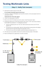
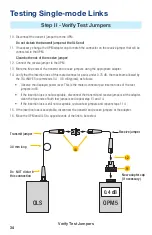
10.  Disconnect the transmit jumper from the OPM.
 

Do not disturb the transmit jumper at the OLS end!

11.  If necessary, change the OPM adapter cap to match the connector on the receive jumper that will be 

connected to the OPM.


Clean both ends of the receive jumper

!

12.  Connect the receive jumper to the OPM.
13.  Mate the free ends of the transmit and receive jumpers using the appropriate adapter. 
14.  Verify that the insertion loss of this mated connector pair is under 0.75 dB, the maximum allowed by 

the TIA (NOYES recommends 0.4 - 0.5 dB typical), as follows:


Observe the displayed power level. This is the mated connector pair insertion loss of the test 
jumpers in dB. 


If the insertion loss is not acceptable, disconnect the transmit and receive jumpers at the adapter, 
clean the free ends of both test jumpers and repeat step 13 and 14.


If the insertion loss is still not acceptable, replace test jumpers and repeat steps 1-14.

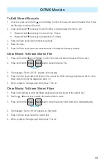
15.  If the insertion loss is acceptable, disconnect the transmit and receive jumpers at the adapter.
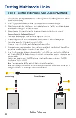
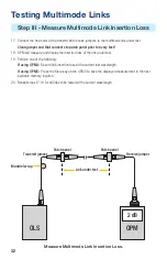
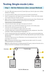
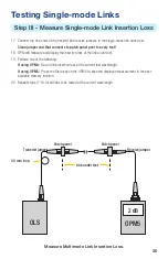
16.  Move the OPM and OLS to opposite ends of the link to be tested.

Verify Test Jumpers

Step II - Verify Test Jumpers 

Testing Multimode Links

OPM

0.4 dB

OLS 

New adapter cap
(if necessary)

Transmit jumper

Mandrel wrap

Do NOT disturb 
this connection

Adapter 

Receive jumper

13

12

11

Содержание Noyes OLS Series

Страница 1: ...eries Light Sources OPM Series Optical Power Meters and Related Test Kits User s Guide www AFLglobal com go NOYES or 1 800 321 5298 1 603 528 7780 Noyes OLS 6 OLS 1 OPM 1 Specs Provided by www AAATesters com ...

Страница 2: ...has been compromised or which have been subject to misuse negligence or accident In no case shall AFL liabilities exceed the original purchase price Exclusions The warranty on your equipment shall not apply to defects resulting from the following Unauthorized repair or modification Misuse negligence or accident CE Information These instruments have been designed and tested to comply with the relev...

Страница 3: ...elect Current File 14 File Manager To Select Current Fiber 14 Test Mode To Set Reference 14 Test Mode To View Reference 15 Recall Mode To View Stored Records 16 To Edit Stored Records 17 Clear Mode To Erase Stored File 17 Clear Mode To Erase Stored Fiber 17 OLS Series Light Sources 18 OLS1 Dual LED Light Source 18 OLS4 Integrated LED and Laser Light Source 23 OLS7 3 Triple Wavelength Laser Source ...

Страница 4: ...l wiring exposed or shorted contact the manufacturer to request servicing WARNING Use only the specified AC adapter Use of another type of AC adapter can damage the instrument and create the danger of fire and electrical shock CAUTION To avoid serious eye injury never look directly into the optical outputs of fiber optic network equipment test equipment patch cords or test jumpers Always assume th...

Страница 5: ...t A test jumper must have the same core and cladding size as the fiber under test The connector at one end of the test jumper must mate with the optical port on each instrument The connector on the other end must mate with the fiber optic system under test A Connector adapter is required to mate fiber optic test jumpers An OPM optical port must be equipped with an adapter cap A variety of adapter ...

Страница 6: ...alibrated wavelengths tone signal Hz wavelength ID references and battery charge status 4 Power Port mini USB connection for AC power adapter or PC connection powers unit only no data functionality OPM Series Optical Power Meters OPM4 Models Optical Power Meter λ Ref dBm OPM4 dB W µ Set 0000 0 00 WAVE ID nm Hz µW dB 0000 0 00 nm Hz µW dB Optical input adapter cap mount Power Port Display Wavelengt...

Страница 7: ...y until HELD AOFF appears Wavelength Backlight key Provides two functions Press and hold to toggle the Backlight on or off Press to cycle through the calibrated wavelengths A Note When the OPM4 is receiving a wavelength ID d light it automatically switches to the ID wavelengths WAVE ID indicator B appears on the display WAVE ID WAVE ID B B A A A 88 88 8888 nm µW 88 88 88 88 8888 8888 dB dBm dB dBm...

Страница 8: ...OPM4 switches to the dB measurement mode Note When setting references from multiple wavelength ID d sources allow several seconds prior to setting the references for wavelengths to be ID d and measured Test Mode To View Reference 1 Press the Ref key to display the stored reference level for the currently selected wavelength or detected WAVE ID wavelength s The reference indicator REF 1 and referen...

Страница 9: ... displays the currently enabled wavelength Single WAVE mode This field displays the detected WAVE ID wavelength Dual WAVE mode This field displays the first detected WAVE ID wavelength Tri WAVE mode This field displays the first WAVE ID wavelength and the third WAVE ID wavelength that is shown on a second page replaces first page automatically in 2 seconds 5 This field displays measured power dBm ...

Страница 10: ...ad on adapter caps 2 Adapter cap the OPM5 optical input must be equipped with an adapter cap 3 Mini USB type B port allows connection to a PC for downloading stored test results interface for AC power adapter 4 Display depending on the selected mode shows measured power dBm or µW or insertion loss dB calibrated wavelengths tone signal Hz wavelength ID references file and fiber number and battery c...

Страница 11: ... File Manager File mode screen File mode press to increment the File number Fiber and Recall mode press to increment the Fiber number Arrow Fiber key Provides several functions Testing mode press and hold to enter the File Manager Fiber mode screen Fiber mode press to decrement the Fiber number File and Recall mode press to decrement the File number Wavelength Backlight key Provides two functions ...

Страница 12: ...cation next Fiber of the current File File Fiber Recall Clear mode press this key to return to the Test mode Recall key Press this key to enter the Recall mode that allows viewing and deleting stored test records Press again to exit the Recall mode Clear The Clear mode screen may be accessed and used as follows From the File mode screen to delete a file From the Recall mode screen to delete a fibe...

Страница 13: ...e currently enabled wavelength Single WAVE mode This field displays the detected WAVE ID wavelength Dual WAVE mode This field displays the first detected WAVE ID wavelength Tri WAVE mode This field displays the first WAVE ID wavelength and the third WAVE ID wavelength that is shown on a second page replaces first page automatically in 2 seconds 5 This field displays measured power dBm or µW or ins...

Страница 14: ...ow Fiber key to enter the File Manager Fiber mode screen 2 A blinking cursor A to the left of Fiber indicates that you are in the Fiber mode FILE FIBS 22 4 A B C D E 3 Use the arrow keys to increment decrement the Fiber number Press and hold arrow key to increment by 10 fibers Press and hold arrow key to decrement by 10 fibers 4 Press the Store key to make the selected Fiber number current and exi...

Страница 15: ...File Management system allows simple organization of power or insertion loss measurements into multiple files Using the supplied Test Results Management TRM software Windows compatible and USB connection test records are transferred to a PC for analyzing generating professional test reports and printing For more information refer to the TRM software User s Guide available on the supplied CD and fr...

Страница 16: ...ow the following data 0 22 0 22 1310 1310 dB dB nm 4 4 FIBR FIBR WAVE ID A B E C D nm Hz A Fiber number B Wavelength C Stored test result D WAVE ID icon if WAVE ID was active when the measurement was taken E Hz icon if Tone was active when the measurement was taken 5 Use the arrow keys to increment decrement the fiber number and view the test result stored in this location Press and hold the arrow...

Страница 17: ...red File to erase 2 Press and hold the Recall Store Clear keys to erase the current file 3 The message Stor to clr FILE appears on the display 4 Press the Store key to delete all fibers for the current file While clearing may take a while for many fibers stored in a file the display will show Clr 5 When complete the display will briefly show FILE Clr Clear Mode To Erase Stored Fiber 1 Press the Re...

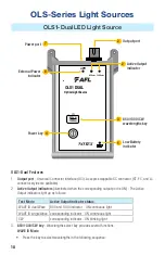
Страница 18: ...D dual Wave 850 and 1300 indicator ON continuous light WAVE ID single Wave corresponding indicator ON continuous light CW corresponding indicator ON blinking light 3 850 1300 CW key Wavelengths select key provides several functions WAVE ID Mode Press the key to select wavelengths in the following sequence OLS1 Dual LED Light Source 850nm 1300nm 9V 850nm 1300nm CW Optical Light Source OLS1 DUAL NOY...

Страница 19: ...300 nm 850 nm Press the key to return to the WAVE ID mode at the currently selected wavelength 4 Power key Press and hold the key until all indicators light up to turn the OLS1 Dual on or off The instrument turns on in its default condition 850 1300 nm Dual mode sending Wavelength ID 5 Low Battery indicator Lights up when a Low Battery condition exists batteries require replacement 6 External Powe...

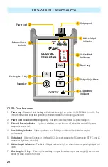
Страница 20: ...ire replacement 5 Output port Universal Connector Interface UCI Accepts swappable SC connector ST FC and LC connector styles are available 6 Active Output indicators The Active Output indicators light up when the corresponding output port is on 7 Wavelengths l key Wavelength select key changes the active output wavelength s as indicated below for each operational mode OLS2 Dual Laser Source 270Hz ...

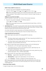
Страница 21: ...t Adjust mode is valid in CW and single WAVE ID modes only Note If the Output Adjust mode is enabled while the OLS2 Dual is transmitting Dual WAVE ID the unit will switch to the 1310nm WAVE ID mode If the Output Adjust mode is enabled while the OLS2 Dual is transmitting any of the Tone frequencies the unit will switch to the CW mode b To enable the Output Adjust mode and begin power change perform...

Страница 22: ...y to select the desired operating mode When the OLS2 Dual operates in WAVE ID Mode WAVE ID indicator on Press the Mode key to switch the unit from the WAVE ID to CW mode The WAVE ID indicator will turn off and the CW indicator will turn on If multiple ID wavelengths were being transmitted the unit will continue to transmit the shortest wavelength 1310nm When the OLS2 Dual operates in CW mode CW in...

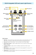
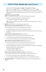
Страница 23: ...eplacement 5 MM output port Universal Connector Interface UCI Accepts swappable SC connector ST FC and LC connector styles are available 6 SM output port Universal Connector Interface UCI Accepts swappable SC connector ST FC and LC connector styles are available OLS4 Integrated LED and Laser Light Source 1310nm 1550nm 850nm 1300nm 9V Tone 1310nm 1550nm 850nm 1300nm OLS4 Optical Laser Source with W...

Страница 24: ...ID mode at the currently selected wavelength 9 1310 1550 CW key Single mode wavelengths select key provides several functions as follows WAVE ID Mode Press the key to select wavelengths in the following sequence Dual 1310 1550 nm 1310 nm 1550 nm Dual 1310 1550 nm Press and hold the key to switch to the CW mode at the currently selected wavelength Note If the OLS4 operates in the Dual WAVE ID mode ...

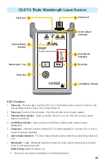
Страница 25: ...rface UCI Accepts swappable SC connector ST FC and LC connector styles are available 6 Active Output indicators The Active Output indicators light up when the corresponding output port is on 7 Wavelength l key Wavelength select key changes the active output wavelength s as indicated below for each operational mode WAVE ID Mode WAVE ID indicator on Press the l key to select wavelengths in the follo...

Страница 26: ...the shortest wavelength When the OLS7 3 operates in CW mode CW indicator on Press the Mode key to switch the unit from the CW mode to 2kHZ Tone mode The CW indicator will turn off and the 2kHz Tone indicator will turn on The unit will start transmitting the selected wavelength with 2kHz modulation When the OLS7 3 operates in 2kHz Tone mode 2kHz indicator on Press the Mode key to switch the unit fr...

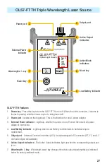
Страница 27: ...lacement 5 Output port Universal Connector Interface UCI Accepts swappable SC connector ST FC and LC connector styles are available 6 Active Output indicators The Active Output indicators light up when the corresponding output port is on 7 Wavelength l key Wavelength select key changes the active output wavelength s as indicated below for each operational mode OLS7 FTTH Triple Wavelength Laser Sou...

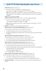
Страница 28: ...nue to transmit the shortest wavelength When the OLS7 FTTH operates in CW mode CW indicator on Press the Mode key to switch the unit from the CW mode to 2kHZ Tone mode The CW indicator will turn off and the 2kHz Tone indicator will turn on The unit will start transmitting the selected wavelength with 2kHz modulation When the OLS7 FTTH operates in 2kHz Tone mode 2kHz indicator on Press the Mode key...

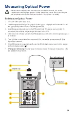
Страница 29: ...apter cap must match the connector on the end of the test jumper you will connect to the OPM 4 Connect one end of the test jumper to the OPM adapter cap and the other end to the optical output to be measured 5 Press the λ key to select the calibrated wavelength that matches the nominal wavelength of the source being measured 6 If the OPM is presently measuring loss dB press the dB dBm key to displ...

Страница 30: ...ary press the dB dBm key to display optical power in dBm 8 If measured output power is outside of the normal range specified by manufacturer clean all fiber connections or replace the transmit jumper Repeat steps 4 7 9 To set the reference level at the current wavelength s on the OPM press and hold the Ref Set key until the label HELD SET is displayed to store the currently measured level or pair ...

Страница 31: ...ollows Observe the displayed power level This is the mated connector pair insertion loss of the test jumpers in dB If the insertion loss is not acceptable disconnect the transmit and receive jumpers at the adapter clean the free ends of both test jumpers and repeat step 13 and 14 If the insertion loss is still not acceptable replace test jumpers and repeat steps 1 14 15 If the insertion loss is ac...

Страница 32: ...If using OPM4 Record link insertion loss at the current test wavelength If using OPM5 Press the Store key on the OPM5 to save the displayed measurement in the next available memory location 20 Repeat steps 17 19 for all links to be tested at the current wavelength Measure Multimode Link Insertion Loss Step III Measure Multimode Link Insertion Loss Testing Multimode Links OPM OLS 2 dB Link under te...

Страница 33: ...e OPM If necessary press the dB dBm key to display optical power in dBm 8 If measured output power is outside of the normal range specified by manufacturer clean all fiber connections or replace the transmit jumper Repeat steps 4 7 9 To set the reference level at the current wavelength s on the OPM press and hold the Ref Set key until the word HELD SET is displayed to store the currently measured ...

Страница 34: ...as follows Observe the displayed power level This is the mated connector pair insertion loss of the test jumpers in dB If the insertion loss is not acceptable disconnect the transmit and receive jumpers at the adapter clean the free ends of both test jumpers and repeat step 13 and 14 If the insertion loss is still not acceptable replace test jumpers and repeat steps 1 14 15 If the insertion loss i...

Страница 35: ...If using OPM4 Record link insertion loss at the current test wavelength If using OPM5 Press the Store key on the OPM5 to save the displayed measurement in the next available memory location 20 Repeat steps 17 19 for all links to be tested at the current wavelength Testing Single mode Links Step III Measure Single mode Link Insertion Loss Measure Multimode Link Insertion Loss 30 mm loop OPM5 OLS 2 ...

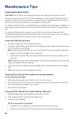
Страница 36: ...fluid Note if using isopropyl alcohol IPA be sure to use 99 pure IPA that has not been contaminated Dampen a portion of the wipe with the cleaning fluid Gently wipe the exposed OPM port starting with the wet section of the wipe and pulling it to the dry section Note Starting with the wet cleaning and finishing in the dry improves cleaning action reduces static buildup and finishes with the end fac...

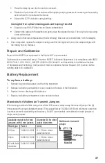
Страница 37: ... STD 45662A ISO Guide 25 and traceability to the National Institute of Standards and Technology Call Customer Service to obtain a Service Request S R number before sending units in for calibration Battery Replacement To replace a battery 1 Remove the protective rubber boot from the instrument 2 Remove the battery compartment cover located on the back of the instrument 3 Replace the two discharged ...

Страница 38: ...Thank you for choosing NOYES Test and Inspection www AFLglobal com go NOYES CERTIFIED ISO 9001 NOYES www AFLglobal com go NOYES or 1 800 321 5298 1 603 528 7780 ...

Отзывы: