HR-16/HR16B Service Manual 1.00
2
2.1 Battery Backup
Battery backup is actually more complicated
than it might first appear, as it depends on a good
system reset (see section 3.1 for details) in order to
function properly. The actual backup circuit consists
of a battery (3V - 3.6V Lithium), a 10K resistor (R97)
for checking standby current (see below), a
"steering" diode (D7), a filter capacitor (C59), and a
transistor/resistor/diode combination that acts as a
steering diode. This combination may be missing on
older board revisions, and must be installed (see
section 7.1) to prevent data corruption due to a
significant difference between Vcc and the amplitude
of the data buss.
SRAM standby current should always be
checked. While the unit is off, check the voltage
across R97. If the voltage is higher than 80mV
(specification, although a 1 to 20mV range is more
normal) then a problem exists. Usually it indicates a
bad (or simply wrong) SRAM, or a short somewhere
along the MEM PWR line. Note that for a short time
Sony 58256-PM (high power) SRAMs were being
installed at the factory, causing batteries to drain in
about 1 year. They should be replaced with low
power versions (58256-LP) when found, in order to
eliminate excess battery drain. We are currently
using Hitachi 62256ALPs as replacements.
CAUTION:
Danger of explosion if battery is
incorrectly replaced. Replace only with the same type or
equivalent type recommended by the equipment
manufacturer.
Battery Manufacturer: Tadiran
Type: TL-5101
Rating 3.6V
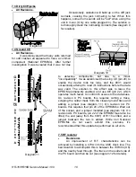
2.2 PUP Circuit
The PUP (quiet Power UP) circuit is designed
to prevent the unit from making noise during power
up. Note that this circuit will not be present on the
earliest main PC boards. The circuit utilizes the
RESET line (section 3.1) to control the power supply
lines to U20, which is the final active stage before the output jacks. Since both rails operate
similarly, we'll only take the time to explain the operation of the + rail.
During power up, the RESET line is held low until the regulators are fully functioning. At this
point, Q11 is turned off by RESET via R104. This has the affect of turning off Q10 by allowing the
base of Q10 to pull high via R101. As soon as the reset line goes low, Q11 will turn on, pulling the
base of Q10 lower. Q10 is now biased into saturation, allowing r12V to be fed to the op-
amps. C65 is provided for extra filtering. The - rail consists of R99, R100, R105, Q12-Q13, and C64.
Diagram 2
Содержание HR-16
Страница 1: ...HR 16B Drum Machine Drum Machine SERVICE MANUAL 1987 Alesis...
Страница 2: ...HR 16 HR16B Service Manual 1 00 i 03 31 06 HR 16 HR 16B Drum Machines Service Manual V1 00 7 27 95...
Страница 38: ...HR 16 HR16B Service Manual 1 00 31 12 0 Service Manual History 7 27 95 V1 00 1st release...
Страница 41: ...HR 16 HR16B Service Manual 1 00 34 NOTES...


