background image


K8M800-754


Hardware Installation 

This section will assist you quickly in installing your system hardware. Wear a wrist ground strap 
before handling components. Electrostatic discharge may damage your system components. 

CPU Processor Installation 

This mainboard supports AMD

®

 Athlon

TM

 64 processor using a Socket 754. Before building your 

system, we suggest you to visit the AMD website and review the processor installation procedures. 
(http://www.amd.com)  

CPU Socket 754 Configuration Steps: 

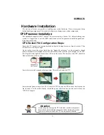
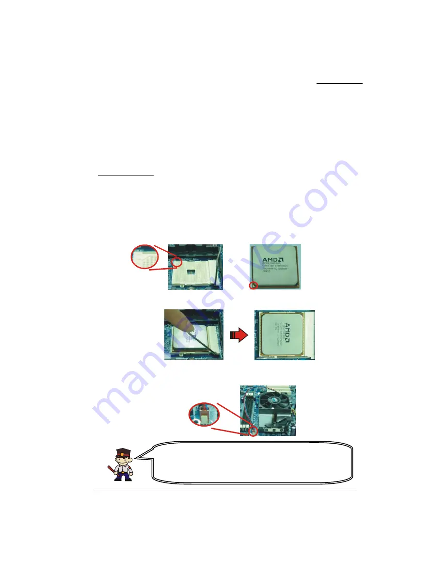
Locate the CPU socket on your mainboard and nudge the locking lever away from the socket. Then 
lift the lever to a 90-degree angle. 

On the socket, locate the corner which has the “diagonally cut-corner” on the rectangular shaped 
pattern of pinholes (see diagram below-left). Match that corner with the “gold triangle” on the CPU 
(see diagram below-right) and lower the CPU onto the socket. The bottom of the CPU should be 
flush with the


 face of the socket. 

Lower the lever until it snaps bac


S ear thermal grease on

e the clasps on the 


k into position. This will lock down the CPU. 


m

 top of the CPU. Lower the CPU fan onto the CPU and us

fan to attach it to the socket. Finally, extend the power cable from the fan and insert it onto the 
“CPUFAN” adapter. 


Attention 

erheating may dam

Ov

age the CPU and other sensitive components. 

Please check the installation completely before starting the system. 
Make sure the heatsink and the CPU fan are properly installed. 

Diagonally 
Cut-corner

Gold triangle

Содержание K8M800-754 Series

Страница 1: ...l the trademarks or brands in this document are registered by their respective owner Disclaimer We make no warranty of any kind with regard to the content of this user s manual The content is subject to change without notice and we will not be responsible for any mistakes found in this user s manual All the brand and product names are trademarks of their respective companies FCC Compliance Stateme...

Страница 2: ...54 Series VIA K8M800 VT8237 Support Socket 754 AMD AthlonTM 64 Prcessor User Manual Dimensions ATX form factor z 210mm x 244mm WxL Operating System z Supports most popular operating systems Windows 2000 XP etc ...

Страница 3: ...inboard contains very delicate IC chips Use a grounded wrist strap when working with the system 0 Do not touch the IC chips leads connectors or other components 0 Unplug the AC power when you install or remove any device on the mainboard Packing list K8M800 754 mainboard IDE Cable FDC Cable USB Bracket optional SATA Power cord SATA Cable optional I O Shield Mainboard Setup Driver CD Mainboard User...

Страница 4: ...TALLATION 6 CPU Processor Installation 6 Memory Installation 7 Back Panel Configuration 9 Front Panel Headers Indication SW LED PWRLED SPEAKER 11 Connectors 12 Jumpers Headers 13 Audio Connectors 15 Slots 16 Power Supply Attachments 17 APPENDIX I SUPER 5 1 CHANNEL AUDIO EFFECTS SETUP 18 APPENDIX II SATA RAID 0 1 SPECIFICATION 19 ...

Страница 5: ...ilt in Serial ATA facilities that support SATA RAID 0 or 1 and transfer rate up to 150 MB sec per channel Moreover the K8M800 754 mainboard has On board Video Graphic function which is able to support 3D and video acceleration With Ultra AGP IITM Technology supported the video performing effeciency can achieve up to 2 GB sec of an AGP VGA card worked The K8M800 754 mainboard comes with an AC 97 au...

Страница 6: ...Tek RTL8100C DRAM Memory z Support DDR400 PC3200 DDR333 PC2700 DDR266 PC2100 SDRAM z Support 64 MB 128 MB 256 MB 512 MB 1 GB unbuffered with or without ECC DIMM modules z Support up to two memory modules with a total capacity of 2 GB PCI BUS Slots z Provide three PCI slots z Include 33MHz 32 bit PCI interface PCI 2 3 is compliant AC 97 Sound Codec On board z High performance CODEC with high S N ra...

Страница 7: ...A 1 0 z Support Serial ATA 150 MB sec transfers rate z Support SATA RAID 0 or RAID 1 mode Green Functionality z Support Phoenix Award BIOS power management function z Contain an inactivity power down timer that can be set from 1 to 15 minutes z System wake up from power saving sleep mode by touching any keyboard or mouse I O facilities z One Multi parallel Port capable of supporting the following ...

Страница 8: ...K8M800 754 Hardware Monitor Function z Monitors CPU Chassis Fan Speed z Monitors CPU system Temperature z Monitors System Voltage 4 ...

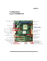
Страница 9: ...IA VT8237 Chip Speaker Power LED Connector AGP Slot VIA K8M800 Chipset CPU Socket DDR Socket X2 ATX Power Connector 24 pin for Rev 1 0 P C B 6 CH AC 97 Audio Codec LAN function Jumper JP2 RealTeL8100C LAN Chip Audio Connector FINTEK F71805F LPC I O chip SFAN2 CD Audio In Front Panel Audio SFAN1 CPU FAN USB Port LAN Connector USB Port KBMS USB Power On Jumper ATX 12V Power Connector JP1 PCI Slot PC...

Страница 10: ...locate the corner which has the diagonally cut corner on the rectangular shaped pattern of pinholes see diagram below left Match that corner with the gold triangle on the CPU see diagram below right and lower the CPU onto the socket The bottom of the CPU should be flush with the face of the socket Lower the lever until it snaps bac S ear thermal grease on e the clasps on the k into position This w...

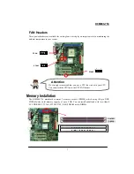
Страница 11: ...on the DIMMs ambient temperature in yo 3 CPAN 1 Memory Inst ation The K8M800 754 mainboard contains 2 memory sockets DIMM which using 184 pin DDR SDRAM with a total memory capaci ECC DDR 400 333 266 PC3200 27 SFAN1 1 3 1 3 SFAN2 Attention We strongly recommend that you use a CPU fan sink with your CPU Yo U fan to the CPUFAN header u can attach the CP D IM M 1 B A N K 0 B A N K 1 D IM M 2 B A N K 2...

Страница 12: ...ure Lower the m thumbs until the Repeat step 1 2 3 for the remaining memory modules ory le Installation The following in explain memory module 1 Before install your memory module please mak structions Pull the white plastic tabs at both ends of the slot away from the slot 2 e notch on the memory module with the corresponding pattern in th that the module will be inserted with the proper orientatio...

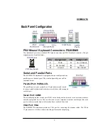
Страница 13: ...o connect into this port for monitor displaying ack Panel Configuration This mainboard provides a standard PS 2 mouse connector and PS 2 Keyboard connector The pin assignments are described below erial and Pa a ts The K8M800 75 is equipped with on parallel port on the back panel The serial and par 4 mainboard explained below ARALLEL Parallel Port P t to connect parallel printers and other dev with...

Страница 14: ... A s S und T The three ports c in Line in and Speaker out ar Channel dr basic au the three o functionality audio ports er you in abled the Super to support and Super 5 1 A your speakers S rd audio port for connecting the speaker W en S ca Line In This port is for connecting an external audio device such as a CD player tape player or other audio devices that provide an audio input When the Super 5 ...

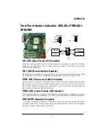
Страница 15: ...ected to a front panel power switc pin to ground for at least 50 ms to signal the power supply to switch on or off the time required is due to internal debounce circuitry on the system board At least two seconds must pass before the power supply will recognize another on off signal PWR LED 3 pin Power LED Header This mainboard provides a 3 pin power LED header on the front panel of a computer case...

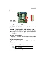
Страница 16: ...rts Ultra ATA 33 Ultra ATA 66 Ultra ATA 100 and Ultra ATA 133 It has two slots IDE1 and IDE2 for connecting the hard drive disks You can expand to connect maximal 4 IDE supported devices such as hard drive disk CD ROM 120M support SATA RAID 0 or 1 IDE1 Primary IDE Connector You can connect up to two hard drive disks to IDE1 If you attach two HDDs you must use a ribbon cable with three connectors Y...

Страница 17: ...ers If you are using USB 2 0 devices with Windows 2000 USB 2 0 driver from the Microsoft website 3 On board LAN function Enabled Disabled JP2 led Disabled JP1 JP3 ket is typical secur an connect to external XP you will need to install the 2 3 Closed Funcon disabled 1 JP2 3 1 1 2 Closed Function enabled JP1 JP3 3 JP2 1 Function enabled T ans to put the jumper cap pins JP2 1 2 Closed he word Closed ...

Страница 18: ...ch as a password is forgotten This jumper allows you to reset the CMOS configurations and then reconfigure it 1 1 Turn off your system and disconnect the ble 2 Set JBAT to OFF 2 3 Closed 3 Wait for several seconds 4 Set JBAT to ON 1 2 closed 5 Connect the AC power cable 6 Reset a new password AC power ca and turn on your system JBAT 3 JBAT 1 1 2 Closed Normal function The wleans to put the jumper ...

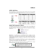
Страница 19: ...ove caps otherwise the front panel audio the dio will disconnect usly CD ROM Audio In Header header is used to connect to a CD ROM D g aud nbo no io ar br d t re remove the jumper caps covering the header pins Connect pi the jumper imultaneo back panel au s AUD _ GND AUD _ RET _ L AUD _ RET _ R AUD _ VCC CD 1 CD AUDIO IN FRONT AUDIO Pin 9 10 AUD_RET_L AUD_RET_R AUD_VCC AUD_GND AUD_FPOUT_L HP_ON AU...

Страница 20: ...ty of the mainboard and your system GP Slot 4X 8X AGP he mainboard is equipped a 2X 4X 8X Accelerated Graphics Port AGP for working with an GA card CI Sl is mainboard is equipped 6 standard PCI slots PCI Peripheral Component Interconnect slots are e bus standard for setting more expansion cards and also has supplanted the older ISA bus standard T ca A T V P ots PCI1 6 Th th ...

Страница 21: ...ectors Connect the 4 pin connector first and then connect another 20 pin connector Make sure these connectors are set in secure before applying power 2 PIN ROW1 ROW 1 3 3V 3 3V 2 3 3V 12V 3 GND GND 4 5V Soft Power On 5 GND GND 6 5V GND 7 GND GND 8 Power OK 5V 9 5V for Soft Logic 5V 10 12V 5V 11 12V 5V 12 3V GND Pin 1 ROW1 ROW2 24 Pin ROW1 2 Pin 1 20 Pin 24 pin block for REV 1 0 P C B only Pin 1 AT...

Страница 22: ...r speakers Super 5 1 Channel Audio Effects This mainboard comes with an ALC655 Codec which supports high quality Super 5 1 Channel au effects With ALC655 you are able to use standard line jacks for surround audio output without connecting to any auxiliary external modules Using this func y u o io applic t a d wi th Hard Speaker Test Make sure the cable is firmly into the connector 1 Click the audi...

Страница 23: ...D 1 mirrored Disk Striping RAID 0 Striping is a performance oriented non multiple disks are used to form a larger virtual disk Data is then striped or mapped across all the physical disks In this way modern SATA and ATA bus mastering technology can be used to perform multiple I O operations in parallel enhancing performance While Striping is discussed as a RAID Set type it actually does not provid...

Отзывы: