


4. Installation of the Components
134
4.3 Installation of the main device
This section describes the way to install the device on a table or a rack. Follow the
procedures below.
When moving the redundant power model, do not hold the handle of the power
supply unit or the fan unit. The handle can come off and the device can fall, which
might cause injury. Or the EPU might be distorted to cause a fire or an electric
shock.
4.3.1 Table mount
This device can be installed on the level, stable, flat surface. The installation procedures
are as follows:
[Step 1]
Flip the EPU upside down on a flat surface.
[Step 2]
Attach the four rubber pads within the marks on the bottom of the EPU.
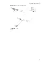
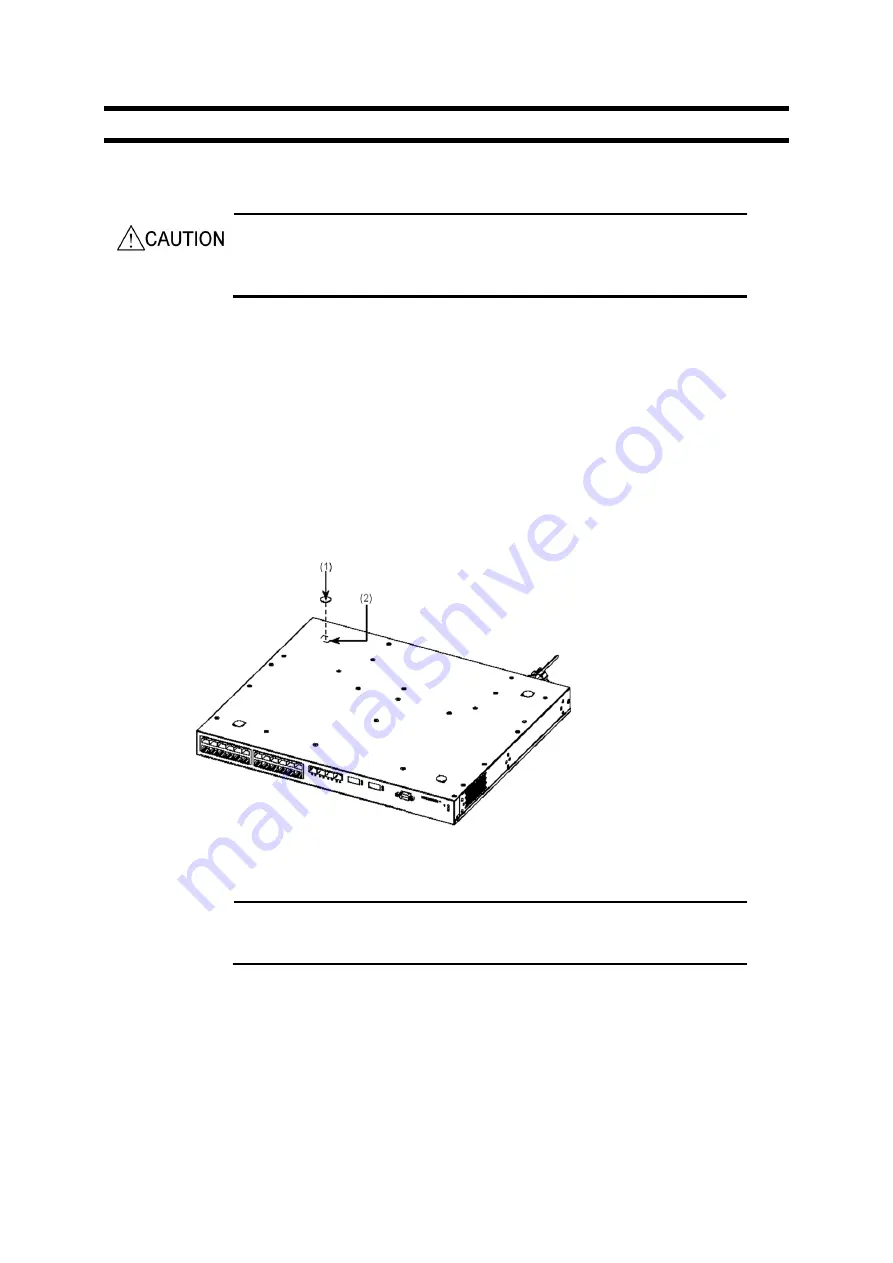
Figure 4-1
Attaching the rubber pads
(1) Rubber pad
(2) Mark
NOTE
Confirm that the position to attach the rubber pad has no dirt. Wipe any dirt off with
a dry cloth before attaching the rubber pad.
[Step 3]
Flip the EPU back over and mount it on the table.
4.3.2 Rack mount
This device can be installed into a 19-inch cabinet rack conforming to the EIA standard.
The procedure is as follows:
Содержание AX2400S series
Страница 3: ...Copyright Copyright C 2005 2011 ALAXALA Networks Corporation All rights reserved ...
Страница 4: ......
Страница 6: ...Preface II Find description from the AX2400S series manuals ...
Страница 7: ...Preface III Find description from the AX3640S and AX3630S series manuals ...
Страница 10: ...Preface VI ...
Страница 14: ...Contents iv ...
Страница 160: ...3 Preparation of Interface Cables and Terminals 130 ...
Страница 214: ...4 Installation of the Components 184 ...
Страница 231: ...5 Expansion Replacement and Removal 201 Figure 5 18 Inserting the fan unit 1 Fan unit slot 2 Fan unit ...