Braddan Shower Tray
Installation And User Care Instructions
Failure to install this AKW product in accordance with supplied instructions or the making of unauthorised modifications will
invalidate any warranty and will affect product safety.
AKW, Pointon Way, Hampton Lovett, Droitwich Spa, WR9 0LR
Tel.+44 (0) 1905 823298 - Fax. +44 (0) 1905 823297 - www.akw-ltd.co.uk
© 2018 AKW
01-018-200-09
To order additional products or parts please call: 01905 823299 or on the details above
Read ALL instructions carefully BEFORE installation and leave with the end user
Sizes Avaliable
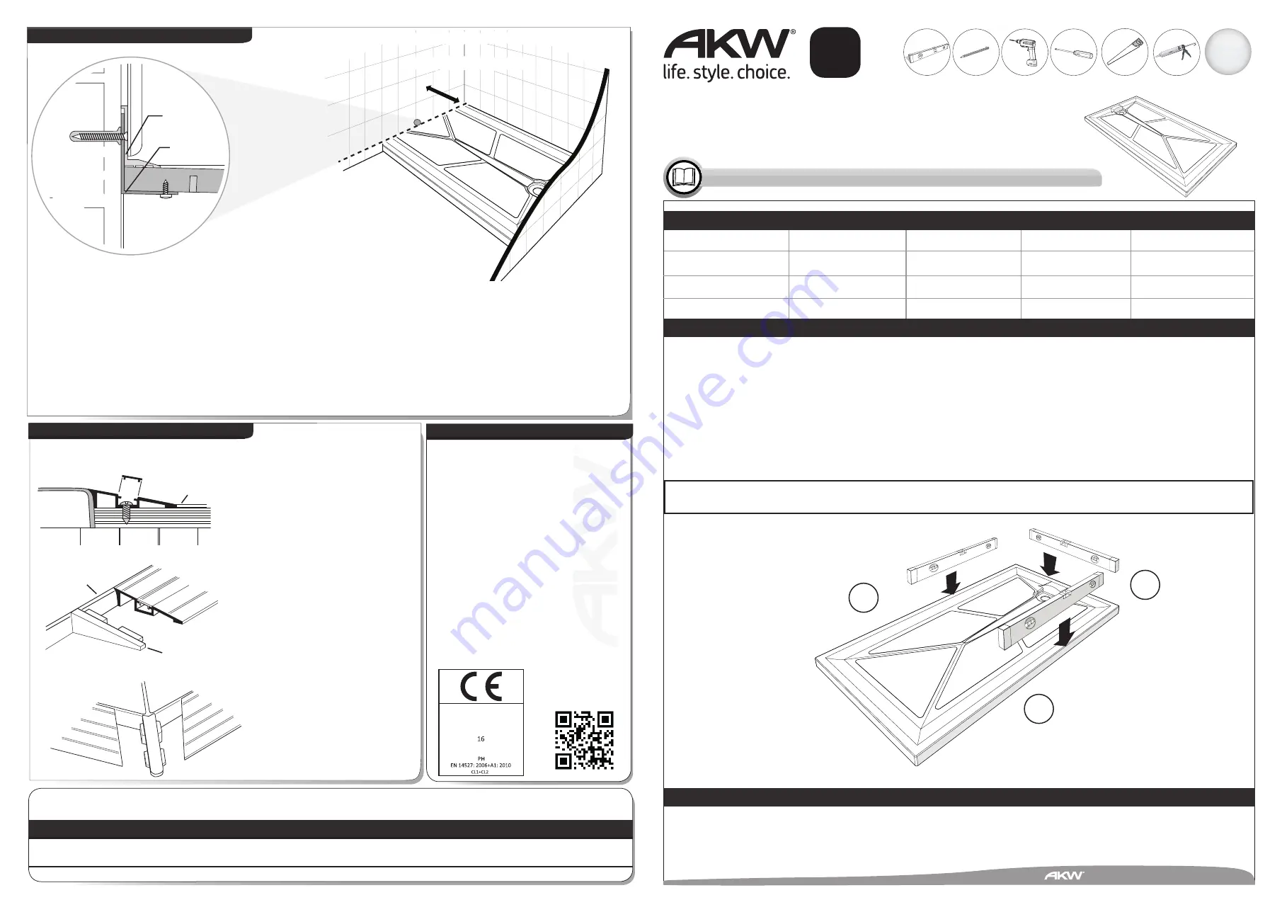
Place ramp onto a level floor and
against tray, ensure ramp is flush
with tray edge and in
appropriate position. Mark off
fixing holes, drill and insert
suitable fixings in the floor.
Apply silicone sealant to contact
area of ramp before fixing with
No.8 x 38mm (1
1
/
2
”) pan head self
tapping screws. Snap in
plastic sections to close fixing
cavity and place end caps to ramp
using adhesive. Note: For ramps
that continue around corner of
tray, a 45º joining piece is
supplied. These ramps may
require cutting to size. Ensure
that silicone is applied between
joining piece and tray and joining
piece and ramp.
(See Figs. 11, 12 and 13)
.
Guaranteed
for
Life
Fig.13
45º joining piece
Step 4 - Braddan Ramps
800x800
820x820
900x900
1000x700
1000x800
1000x1000
1200x650
1200x700
1200x760
1200x820
1200x900
1300x700
1300x820
1420x700
1420x820
1500x700
1500x820
1700x700
1800x700
1800x820
Installation
IMPORTANT
Before completing the installation, water test the flow from tray into waste for correct installation and drainage efficiency.
It is important to ensure that the floor is level in all directions before putting the tray into place. If water puddles away from
the waste, this is a clear indication that the levels are not correct - the water is acting as a ‘spirit level’.
The sides on the tray
A
and
B
may well show level on testing, but if point
C
is low, then water will puddle in the area of point
C
and the only remedy is to level the floor and refit the tray. The tray has ‘lands’ on all four sides.
Use a spirit level front to back and side to side - all ‘lands’ must be level (
ABC
) - the fall is moulded into the tray
(See Fig. A)
.
It is not necessary to remove plaster from the walls for installing the above trays. When tiling, ensure that the bottom row of
tiles are bedded in to align with the final position of the tray.
Fig. A
The Braddan Shower Tray should be cleaned periodically to remove any accumulation of hair or other waste material, using
normal domestic bathroom cleaning materials. Do not use strong or concentrated acidic, alkaline or other cleaning materials as
these may damage or discolour the product. After cleaning always flush down with water then wipe thoroughly with a damp
cloth to remove any cleaning material residues before drying off.
Available Sizes (mm)
Usercare Instructions
End Cap
Silicon Seal
Snap in
Vinyl Flooring
Flush
Fig. 11
Fig.12
UK
UK
UK
UK
5mm
4mm
3mm
A
B
C
Technical Help line
01905 560219
Technical Help line
01905 560219
Orderline
01905 823299
General Enquiries
01905 823298
Fax
01905 823297
Website
www.akw-ltd.co.uk
Quotes & orders email
Enquiries email
Contact
ALL GRP TRAYS
Label for
Product
Packaging
Manual
Note
DoP numbers are
Braddan
Tri-form
09-012-075
GRP Braddan
01-018-330
Sulby
01-018-331
Sulby 2
01-018-332
Multi Spec
01-018-333
Low Profile
01-018-334
DoP 01-018-330
07-003-050
DoP
DoP 01-018-330-02
07-003-050-02
DoP
AKW Limited
Pointon Way, Hampton Lovett
Droitwich Spa, WR9 0LR
United Kingdom
www.akw-ltd.co.uk
AKW Limited
Pointon Way, Hampton Lovett,
Droitwich Spa, WR9 0LR
United Kingdom
www.akw-ltd.co.uk
DoP 01-018-330-02
07-003-050-02
DoP
For latest AKW news and
products, scan this code
with your phone or tab
device.
300mm MAX Cut down length
See Instructions 07-003-020 for more information on Cut-to-length.
The Braddan 1800 tray has a cut to length area that can be cut to suit the dimension between walls down to 1500mm.
Use a fine toothed blade in either jigsaw or handsaw (cut from below with jigsaw or from above with handsaw).
Allow for thickness of trim angle ‘B’ (2mm or
1
/
8
”) when cutting tray to size
(See Fig. 10)
.
After trimming tray and angles A & B to size, mastic underside of tray in position of angle ‘B’ placement. Fit angle ‘B’ to
underside of tray with stainless steel screws. Place tray onto a prepared level floor and between walls, ensuring that angle
‘B’ is tight against end wall. Place angle ‘A’ onto tray and against angle ‘B’ then drill 4.5mm (
3
/
16
”) diameter holes on ‘v’ groove
location through both angles (drill countersunk holes in angle ‘A’). Remove angle ‘A’ then drill through previously drilled holes in
angle ‘B’ with a No.10 / 5mm masonry drill into wall and fit plastic wall plugs. Silicone seal undersides of angle
‘A’ then fix to wall with No. 8x38mm (1
1
/
2
”) countersunk head stainless steel screws. Silicone seal between angle ‘A’ and tray if
required. If required the trimmed tray edge is now ready for end moulding.
(See cut-to-length instructions 07-003-020)
.
Step 3 - Cutting 1800mm Tray to length
Fig. 10
No.8 x 13mm
(
1
/
2
”
) Pan Head
Screws
Angle A
Angle B
4.5mm (
3
/
16
”
)
dia. holes
No.8 x 38mm
(
1
1
/
2
”
)
Countersunk
Screws


