

1.
Choose a dry and dust free place for installation. Remove the faceshield from
your helmet. Thoroughly clean and dry the entire faceshield (outside and inside)
per manufacturer’s instructions, or with a mild detergent and water. Remove all
fingerprints, grease residues, dirt, and moisture.
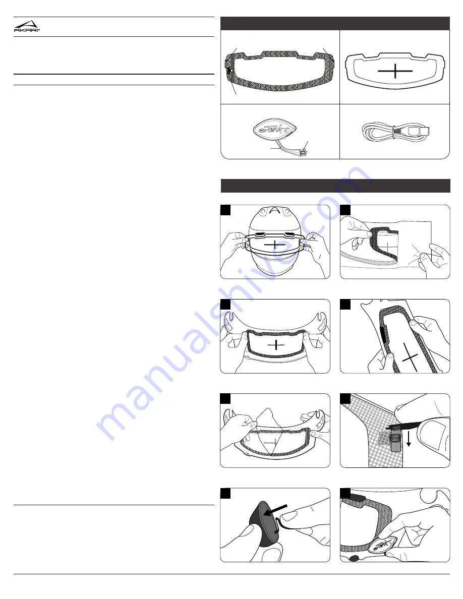
2.
Reinstall the face shield to your helmet. Be careful to avoid touching the inside
of the faceshield or the inside surface of the insert, in order to keep both free of
fingerprints.
3.
Peel the vinyl installation template from its backing. With your helmet faceshield
down and fully closed, center the installation template on the outside surface of
the faceshield. Align the template within the perimeter of the helmet portal so that
it fits within the opening
(Diagram 1)
.
4.
Leaving the vinyl installation template in place, remove the faceshield from the
helmet. Set it face down on a soft surface. Avoid contact with the inside surface
of the faceshield to keep it free of smudges or fingerprints.
5.
Carefully peel the Akari
®
AX12-ARAI insert from the clear liner
(Diagram 2)
.
6.
Hold the AX12-ARAI insert by the edges of the adhesive vinyl and gently bend
into a “U’ shape. Align the crosshairs of the visor insert with the crosshairs of the
vinyl installation template
(Diagram 3)
. When correctly positioned, gently apply
the AX12-ARAI insert to your faceshield.
7.
Moving from the center outwards, mount the insert by pressing along the vinyl
border. Do NOT PRESS ON THE LIQUID CRYSTAL VIEWING AREA
(Diagram 4)
.
They vinyl border should be adhered flush against the faceshield. A gap between
the liquid crystal viewing area and the faceshield will be expected.
8.
Gently peel the clear installation template off of the AX12-ARAI
(Diagram 5)
.
Remove the vinyl installation template from the outside of the faceshield. NOTE: It
is recommended to save the installation templates if you feel you will transfer your
Akari
®
AX12-ARAI to another faceshield at a later time.
9.
To connect the AX12-ARAI button, first remove the adhesive liner from the back
of the flexible ribbon. Next, snap the connector at the end of the ribbon onto the
connection point of the AX12-ARAI insert
(Diagram 6)
. Wrap the ribbon under the
faceshield and remove the liner from the back of the AX12-ARAI button. If there is
extra length of the ribbon hanging loose, you may shorten it by folding a small sec-
tion and pressing the extra length onto the back of the adhesive foam
(Diagram 7)
.
10.
CAUTION! Once mounted, the AX12-ARAI button is intended to be perma-
nent. You may not reposition or transfer the button once it is mounted to your
faceshield. Doing so may cause permanent damage to the button and will require
a replacement. Horizontally mount the button on the outside surface of the
faceshield. The button should NOT overhang the faceshield
(Diagram 8)
. Press
the button firmly into place to ensure solid adhesion. Secure the flex into place by
pressing it onto the faceshield.
11.
Reinstall the faceshield to your helmet. Before operating in automatic mode,
test the insert to make sure the light threshold is set to your desired comfort level.
See “Directions of Use” to set a custom light threshold.
12.
Charge the insert by using the supplied Micro-USB cable. See additional
charging information below.
TO TRANSFER THE INSERT:
Unplug the button from the AX12-ARAI insert.
Starting with the tab on the edge of the insert, gently peel the AX12-ARAI from
your faceshield. Follow directions (1-8) above to re-install the insert onto your
faceshield. NOTE: The AX12-ARAI insert may be removed and transferred to a
new faceshield, although the AX12 button is not transferrable. You may purchase a
replacement AX12 button by visiting your local dealer or www.e-tintproducts.com.
Please read all instructions carefully before use. You may also view a digital ver-
sion of these instructions at www.e-tintproducts.com.
COPYRIGHT ©2017 E-TINT, LLC
MAN-1009 REV.20170314
INSTALLATION
AX12 ARAI
OWNER’S MANUAL
AX12 ARAI INSERT
AX12 BUTTON
INSTALLATION TEMPLATE
MICRO-USB CABLE
PARTS KEY
connection point for AX12 button
removal tab
connector
®
flexible ribbon
removal tab
1
VINYL INSTALLATION TEMPLATE
2
3
4
5
6
7
8
installation diagrams
VINYL INSTALLATION TEMPLATE


