


ATDDC4 Series Installation & User’s Guide
Page 6
Attaching Conduit
The Electrical Supply can be brought into the ATDDC4 enclosure from
any of the
top
three vent-hole positions, from the
back
, or from either
side
.
Conduit access is not available from the bottom.
Note: Optional plastic end-panels may be ordered (left VIS1551-L),
(right VIS1551-R) that have access holes pre-drilled to allow side
access.
If Conduit access is through either of the optional plastic end-
panels, Conduit should NOT be used to support the weight of the
Clock. The Clock must be properly secured to a wall.
Remove the vent cap from the selected mounting hole (if not accessing
through side panels). Attach the conduit with locking nut and extend
the wires into the enclosure.
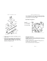
Making the Connection
1.
Slide the circuit board with display part-way back into the case.
Connect the two black wires from the circuit board to the power-
wires from the power cord or conduit using wire nuts. Connect the
Ground Wires from the circuit board and from the power source
(usually green) to the green ground screw on the inside of he
enclosure.
2.
Slide the circuit board fully into place, then slide the front lens
into place.
Note:
the inside of the lens has a paper backing
which should not be removed
.
The end with wider paper should
go to the right
.
Replace the end caps and secure with the two
Phillips head screws.
3.
When the clock is energized, it will set itself, upon receiving the
AirTime radio signal.
ATDDC4 Series Installation & User’s Guide
Page 7
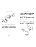
Double Mount – Wall
The ATDDC4 SERIES requires optional mounting kit (SAM0625)
Tools required for mounting the clock:
•
Flat blade screwdriver
•
Phillips head screwdriver
•
15/16" open end wrench
The double wall mount plate attaches to a double or single gang box
installed securely in the wall. Required wiring should be available
through the gang box at time of installation.
Installation Steps
1.
Remove the two chase nipples from the mounting plate posts.
2.
Secure the mounting plate securely to the gang box with the proper
screws. (not supplied)
Note: The long dimension of the mounting plate must be perpendicular
to the ground to assure proper alignment of wall clocks.
See remaining Wall or Ceiling mount instructions below
Double-Mounting - Wall
1.
Place the two clock enclosures back to back and secure by inserting
a #10 screw through the four mounting holes using lock washers
and nuts supplied with the mounting kit.
2.
Attach the modified end cap to the clock’s end to be attached to
the wall mount plate using the original end cap screws.
3.
Align the holes of end cap support plate with the holes in the
modified end cap and secure with 4 #6 Phillips head screws
(supplied).
4.
Line the two posts from the mounting plate up with the two holes
of the modified end cap. Insert the chase nipples through the holes
of the modified end cap and secure to the mounting plate with a
15/16" wrench.


