


ATDDC4 Series Installation & User’s Guide
Page 4
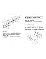
Mounting to a Wall
After deciding where to mount the clock, make two marks 12" apart
and horizontal.
Note: If mounting near a ceiling, make sure the holes
are at least 2 1/4" away from the ceiling. Also, provide at least 16" of
side clearance on one side in order to remove the front panel.
Installation Steps
1.
Drill a 5/16" hole at each mark
2.
Insert a wall anchor and tap it flush to the wall with the hammer.
3.
Insert a screw into each wall anchor leaving 1/4" exposed.
4.
Line up the two keyholes on the back of the case and slip over the
two screws and tighten securely. ( The lower mounting holes can
be marked at this point, the case removed, holes drilled and wall
anchors installed if so desired)
Mounting to a Single Gang Box
Two mounting holes are located in the center of the case 2 1/4" apart
for mounting to a single gang wall box. A 7/8" hole is located between
the mounting holes that will accommodate conduit, if desired.
Note: If mounting near a ceiling, make sure the holes are at least 2-
1/4" away from the ceiling. Also, provide at least 16" of side clearance
on one side in order to remove the front panel.
Line the two holes in the case up to the single gang box and insert
proper screws for the single gang box and tighten securely.
ATDDC4 Series Installation & User’s Guide
Page 9
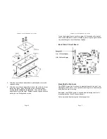
Double Mount - Ceiling
Requires optional mounting kit (SAM0626)
Double-Mounting - Ceiling
Note: Make sure you have at least 16" of side clearance on one side in
order to remove the front panel assembly.
1.
Place the two clock enclosures back to back and secure by inserting
a #10 screw through the four mounting holes using lock washers
and nuts supplied with the mounting kit.
2.
Note: If the ATDDC4 clocks will be mounted too near a wall on one
side to secure the end caps, install the "wall side" end caps now.
3.
Remove the center vent cap from the top of each ATDDC4 clock.
4.
Line the two posts from the mounting plate up with the vent holes
of the ATDDC4 clocks. Insert the chase nipples through the vent
holes and secure to the mounting plate with a 15/16" wrench.


