background image

MN-754 • 071411 • ECR 7999

For maximum effectiveness and safety, 

please read these instructions completely 
before proceeding with installation.

Failure to read these instructions can result in an 

incorrect installation.

INSTALLATION GUIDE

Air Lift


PERFORMANCE

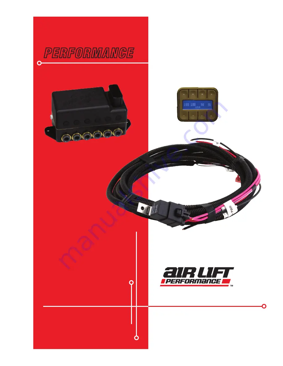
AutoPilot V2

P A T E N T   P E N D I N G

Содержание 27672

Страница 1: ...ess and safety please read these instructions completely before proceeding with installation Failure to read these instructions can result in an incorrect installation INSTALLATION GUIDE Air Lift PERFORMANCE AutoPilot V2 P A T E N T P E N D I N G ...

Страница 2: ...0 Hose Cutter 1 11217 P Clamp 1 24672 Fuse spade 3amp 1 24547 Fuse spade 30amp 1 24500 ATC Fuse holder w cap 2 24645 16GA Butt Connector 1 24752 12 10GA Butt Connector 3 24748 12GA Ring Terminal 3 8 2 24524 Female Spade Terminal 1 24595 12GA Female Spade Terminal 1 24561 Adaptor Mini Fuse 1 24542 ATC ATO Fuse Adaptor 1 17173 1 4 14 X 3 4 Self Tapping Screw 1 17263 1 4 14 x 1 Self Tapping Screw 3 1...

Страница 3: ...r in various locations in this publication Information which is highlighted by one of these notations must be observed to help minimize risk of personal injury or possible improper installation which may render the vehicle unsafe Notes are used to help emphasize areas of procedural importance and provide helpful suggestions The following definitions explain the use of these notations as they appea...

Страница 4: ...or body is mounted inside the vehicle attach filter to port on end of compressor fig 15 If compressor is located outside the vehicle snorkel inlet filter to dry location inside vehicle using components supplied with compressor 2 Center punch and drill four holes using the template on page 19 3 Attach using the hardware supplied with the compressor If the harness must be lengthened use properly siz...

Страница 5: ...e replaced The tank will need to be purged periodically to reduce eliminate the potential of moisture entering the manifold Tank install see fig 15 1 Using the tank feet as a template drill holes for hardware assembly 2 Attach the tank using the supplied hardware 3 Cut an appropriate length of hose from the manifold port T to the PTC fitting on the filter 4 Route the drain fill air line with a sch...

Страница 6: ...R LINES Use a standard hose cutter Air Lift part number 10530 or razorblade Cut all hose ends square and as smoothly as possible 1 Route and attach the air lines to the air springs Route air lines free from abrasive edges and heat sources 2 Attach manifold port FL to the front drivers side left spring 3 Attach manifold port FR to the front passengers side right spring 4 Attach manifold port RL to ...

Страница 7: ...ass connection use a braided leader hose for this moving connection AutoPilot V2 is an advanced pressure based air suspension control system that uses state of the art software algorithms to calibrate or map the control system to your vehicle Once the system is calibrated the algorithm predicts required valve open time to move the air suspension to achieve preset target pressures AutoPilot V2 has ...

Страница 8: ...d in table 2 Calibrate to your vehicle Press button 2 to enter CALIBRATE fig 3 Press button 1 SYSTEM CAL fig 5 follow instructions to calibrate AutoPilot V2 system to your vehicle Once calibration is complete Press buttons 1 5 simultaneously to exit to settings and diagnostics mode TANK MAX 175 fig 4 1 TANK ADJUST 2 CALIBRATE 3 BACKLIGHT 4 PRESET MAIN fig 3 CALIBRATION MENU 1 SYSTEM CAL 2 ADJUST S...

Страница 9: ...haust the tank to the specified MIN tank pressure then turn ON the compressor and measure its inflate time to achieve MAX pressure fig 9 AutoPilot V2 will record this fill time allowing the operator to compare future fill times to determine compressor performance Press buttons 1 5 simultaneously to exit Press button 6 fig 8 to view the number of hours the compressor has been running Rise on Start ...

Страница 10: ...ets can be Low set pressures to the lowest possible pressures for extreme low driving stance Front up for speed bump or driveway clearance Rear up for added load of passengers equipment Play for those that want to enjoy their air suspension freedom AutoPilot V2 has a special function that recognizes side to side presets When left side pressures are equal and right side pressures are equal but 25PS...

Страница 11: ...rop may reduce system performance and durability Examples ECU Fuel pump etc Second compressor signal wire AL034 30 AMP fuse AL005 AL002 AL004 Butt connector 1 2 3 4 5 6 7 8 RR LR RF LF Relay schematic reference 30 30 86 86 85 85 87 87 Compressor OUT 7 Compressor OUT 7 To 12 Volt Battery Source To 12 Volt Battery Source 30 AMP 30 AMP Back View Back View ALOO2 ALOO2 Gray 20GA To Manifold Gray 20GA T...

Страница 12: ...n kit LEFT RIGHT LEFT RIGHT AL005 AL007 Attach filter Drain fill valve mount in accessible location Filter Exhaust 1 4 Elbow Mount to bottom tank port Good Cut Poor Cut Top view of filter This is a moisture drain and must drain to the outside of the vehicle This option must be used for tank P N10995 OPTION 1 INSTALL TO TANK OPTION 2 REMOTELY MOUNT FILTER INSTALLATION OPTIONS AIR LINE CUTTING fig 1...

Страница 13: ...lay shows PLEASE WAIT as it iterates then will flash SUCCESSFUL when achieved or UNSUCCESSFUL if not able to achieve the target pressure window 3 Micro adjust to 1 PSI If more accuracy is desired double press the same preset and the system will refine pressures closer to target This is often necessary when target preset pressures are LOWER than current pressure Accuracy can be improved by rolling ...

Страница 14: ...p will not corrode the metals aluminum brass steel with which it comes into contact PROBLEM CAUSE SOLUTION Compressor doesn t run There is a blown fuse or relay bad ground or poor electrical connections Replace the fuse check the ground wire or check the compressor connector Compressor runs all the time The compressor relay is defective or there is a leak Replace the relay or locate the leak and r...

Страница 15: ...MN 754 Air Lift Performance Electrical Schematic fig 18 AUTOPILOT V2 GEN 3 PRESSURE CONTROL Sold separately Air Lift Part Number 27679 AUTOPILOT V2 SECOND COMPRESSOR HARNESS ...

Страница 16: ...MN 754 Air Lift Performance AutoPilot V2 Remote Control Unit Dimensions 75 2 375 2 875 Side View Top View ...

Страница 17: ...MN 754 Air Lift Performance 6 35 Manifold Template ...

Страница 18: ...MN 754 Air Lift Performance 16380 Compressor Template 6 6900 3 3100 HOLE PATTERN FOR BOTTOM OF 16380 COMPRESSOR ...

Страница 19: ...harges of the product Air Lift Company reserves the right to change the design of any product without assuming any obligation to modify any product previously manufactured This warranty gives you specific legal rights and you may also have other rights that may vary from state to state Some states do not allow limitations on how long an implied warranty lasts or allow the exclusion or limitation o...

Отзывы: