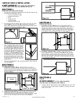
NOTE:
If damper detaches from unit, reattach by snapping the collar back onto the unit. It is
designed to only fit one way.
SECTION 5
Wiring
CAUTION:
MAKE SURE POWER IS SWITCHED OFF AT SERVICE PANEL BEFORE
STARTING INSTALLATION.
CAUTION:
ALL ELECTRICAL CONNECTIONS MUST BE MADE IN ACCORDANCE
WITH LOCAL CODES, ORDINANCES, OR NATIONAL ELECTRICAL CODE. IF YOU ARE
UNFAMILIAR WITH METHODS OF INSTALLING ELECTRICAL WIRING, SECURE THE
SERVICES OF A QUALIFIED ELECTRICIAN.
1.
Wiring Fan/Light Independently:
Run wiring from an approved wall switch carrying the
appropriate rating. One neutral (white), one ground (green or bare copper), and two hot
(black lead connected to the switch). Secure the electrical wires to the housing with an
approved electrical connector. Make sure you leave enough wiring in the box to make the
connection to the fan’s receptacle.
1a. From where you have access to inside the fan’s junction box, connect the one white wire
from the house to both the white wire from the fan’s light receptacle and the white wire
from the fan’s exhaust receptacle. Connect the first black wire from the wall switch to the
red wire from the fan’s light receptacle. Connect the second black wire from the switch to
the fan’s exhaust receptacle. Connect the ground wire from the house to the green wire
from the fan’s grounding screw
(Figure 8).
Use approved methods for all connections.
2.
Wiring Fan/Light together:
Run wiring from an approved wall switch carrying the
appropriate rating. One neutral (white), one ground (green or bare copper), and one hot
(black lead connected to the switch). Secure the electrical wires to the housing with an
approved electrical connector. Make sure you leave enough wiring in the box to make the
connection to the fan’s receptacle.
2a. From where you have access to inside the fan’s junction box, connect the one white wire
from the house to both the white wire from the fan’s light receptacle and the white wire
from the fan’s exhaust receptacle. Connect the black wire from the wall switch to both the
red wire from the fan’s light receptacle and the black wire from the fan’s exhaust receptacle.
Connect the ground wire from the house to the green wire from the fan’s grounding screw
(Figure 9)
. Use approved methods for all connections.
www.airkinglimited.com
210572063 Rev. C 1-13
3 of 12
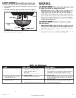
SECTION 6
Completing the Installation
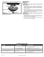
1. Reinstall the fan’s venturi by holding it at approximately a 45 degree angle, hook the two
tabs on the venturi into the slots on the housing and secure in place by tightening the
venturi screw. Rotate the blower wheel by hand to ensure it spins freely. Now plug the
fan motor into the receptacle
(Figure 10).
2. Remove glass light lens from grill by unscrewing knob at the top of lens
(Figure 11).
3. Plug cord from lamp holders into the appropriate receptacle
(Figure 12)
.
4. Line up slots in the grill with lances on inside of housing. Insert included #8 screws
through grill slots and into housing lances. Tighten both screws until the grill fits snugly
to the ceiling. DO NOT OVER TIGHTEN
(Figure 13).
CAUTION:
FAILURE TO SECURE THE REFLECTOR BOLT MAY RESULT IN A
RATTLING OR HUMMING NOISE.
5. Install 2 - 60 watt maximum, type A19 medium base incandescent bulbs (not included).
Figure 10
Figure 7
Supply
from
house
White
Hot (Black)
Ground
Figure 8
Hot (Red)
Figure 9
Supply
from
house
White
Hot (Black)
Ground
Hot (Red)
Figure 11
Glass Lens
Knob
Figure 12
Cord
Lamp
Holder
Figure 13
#8 Screws
Lances
Grill

