background image

6. System Configuration

air

avionics

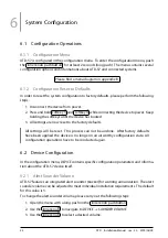
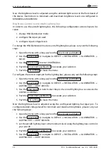
2. Use the inner knob to navigate to

DEVICE

INSTALLATION

SWITCHES

NO

WARNINGS

or

DEVICE

SWITCHES

ORIENTATION

.

3. Use the inner knob to select a source:

IN1

(input on upper connector),

IN2

(input on

lower connector), or

NOT CONNECTED

.

4. Push the inner knob pushbutton to execute your selection.
5. Push the ESC softkey to leave the menu.

6.2.6 Info

In the

DEVICE

menu,

INFO

contains specific information about the ATD-57 device such as

hardware and software version information and the version of the database on the microSD
card (if present).

6.3 Traffic View Configuration

In the configuration menu,

TRAFFIC VIEW

holds data display and user interface parameters.

6.3.1 Units

Units for distance, altitude and vertical speed are configurable:

Distance: kilometers, nautical miles, or statute miles.

Altitude: meters or feet.

Vertical rate: meters per second, feet per minute, or knots.

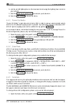
To change the units configuration, please carry out the following steps:

1. Open the menu with a long push on the inner knob pushbutton .
2. Use the inner knob to navigate to

TRAFFIC VIEW

INSTALLATION

UNITS

DISTANCE

,

ALTITUDE

, or

VERT RATE

.

3. Use the inner knob to select the desired unit.
4. Push the inner knob pushbutton to execute your selection.
5. Push the ESC softkey to leave the menu.

6.3.2 Dark Style

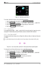
Main display colors can be selected to be black on white (default) or white on black. ‘‘Dark
Style’’ (white on black) is recommended for night flying.

26

ATD

·

Installation Manual

·

rev. 3.0

·

2019/05/09

Содержание ATD-11

Страница 1: ...s AIR Traffic Displays Installation Manual Document MAN0020A0003 Version 3 0 Date 2019 05 09 Phone 49 0 6224 82 83 87 0 Fax 49 0 6224 82 83 87 7 Internet https www air avionics com Mail support air av...

Страница 2: ...air avionics 2 ATD Installation Manual rev 3 0 2019 05 09...

Страница 3: ...obias Fetzer 1 5 2017 04 21 Release M F rderer Added infos regarding bootloader up date Tobias Fetzer 2 0 2017 05 22 Release H Hoeth Document restructuring Hendrik Hoeth 2 1 2017 06 23 Release M F rde...

Страница 4: ...aces 12 Power and Lighting Functions 14 Discrete Inputs 15 Installation Overview 16 General Handling Recommendations 16 Workmanship 16 Cabling and Wiring Considerations 17 Mounting Considerations 17 A...

Страница 5: ...nce Checks 31 Version Revision 31 Configuration and Checkout Documentation 32 Configuration Documentation 32 Checkout Documentation 32 Maintenance 33 Software and Database Loading 33 Cleaning 36 Assem...

Страница 6: ...s air avionics Checkout Log 52 Installation 52 Ground Checks 52 Device Configuration 52 Documentation 52 Configuration Log 53 Device 53 View 54 Traffic System 54 iv ATD Installation Manual rev 3 0 201...

Страница 7: ...d abilities set forth above Refer to section Limitations for additional information and other considerations Allscreenshotsusedinthisdocumentarecurrentatthetimeofpublication Screenshotsareintended top...

Страница 8: ...1 General Description air avionics Figure 1 1 View of AIR Traffic Display 11 Figure 1 2 View of AIR Traffic Display 57 2 ATD Installation Manual rev 3 0 2019 05 09...

Страница 9: ...with a 2 inch ATD 57 or 2 7 inch ATD 11 ATD 80 screen diameter It features field updateable software and is capable of using traffic databases e g FLARMNet from a mass storage device microSD card ATD...

Страница 10: ...ATEC ECW 100 FLARM GPS and Traffic Data Protocol Version 7 19200Bd or higher ZAON Flight Systems XRX TIS GARMIN TIS Output While many factors have to be carefully taken into account it is recommended...

Страница 11: ...e shutdown 8 V DC Current nom 0 07 A Optical Brightness 0 2 1350 cd m2 Viewing Angle 45 LCD Viewing Area 40 5 x 32 2 mm LCD Viewing Envelope 45 45 45 45 1 5 3 Characteristics of the ATD 80 Parameter D...

Страница 12: ...20 g Vibration DO 160D U F F1 Vibration DO 160D S M 1 5 5 Housing and Human Machine Interface ATD has an all metal housing with anti reflective blackout finish on all parts visible to the flight crew...

Страница 13: ...buttons Figure 1 5 Housing and human machine interface overview ATD 57 Figure 1 6 Housing and human machine interface overview ATD 80 1 6 Regulatory Compliance 1 6 1 ETSO Functions ATD does not provid...

Страница 14: ...r applicable airworthiness requirements Installation must follow acceptable practices 1 7 Liability IN NO EVENT WILL AIR AVIONICS BE LIABLE FOR ANY INCIDENTAL SPECIAL INDIRECT OR CONSEQUENTIAL DAMAGES...

Страница 15: ...ntactAIRAvionicsorvisithttp www air store eu 1 9 Installation Materials 1 9 1 Tools required but not supplied Standard Tools Tool Specification Description Phillips screwdriver PH 00 Screwdriver for s...

Страница 16: ...ng harnesses and not supplied Wire MIL W 22759 16 or equivalent Shielded wire MIL C 27500 or equivalent D SUB 15HD FEMALE connector crimp type preferred and crimp inserts D SUB 15HD connector backshel...

Страница 17: ...d ATD 57 View from the back Both connectors are D SUB 15 high density male types Small pin numbers are molded into the connectors for easier pin identification Pin numbers of mating female connectors...

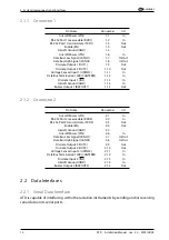
Страница 18: ...BZZOUT1 1 15 Out 2 1 2 Connector 2 Pin Name Pin number I O Aircraft Power VIN 2 1 In RS 232 Port 2 receive data RXD2 2 2 In RS 232 Port 2 transmit data TXD2 2 3 Out Enable EN 2 4 Out Aircraft Ground...

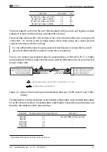
Страница 19: ...be connected using a single cable TRAFFIC SYSTEM RS 232 send data TX TRAFFIC SYSTEM RS 232 receive data RX TRAFFIC SYSTEM Ground GND TRAFFIC SYSTEM POWER VIN DISPLAY SYSTEM RS 232 receive data RX DISP...

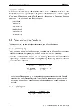
Страница 20: ...or 1 and connector 2 provide power All pins of one connector should be connected If required pins on both connectors may be connected Connector 1 and connector 2 power pins are internally decoupled Th...

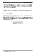
Страница 21: ...bus In aircraft certified for VFR night operations the lighting bus interface is mandatory 2 4 Discrete Inputs A NO WARNINGS SWITCH or a NORTH UP SWITCH or both can be connected to either one of the...

Страница 22: ...ly processes toachievethedesireddurabilityandreliabilityforsubassemblyinterconnections specifically thoseinprintedwiringassembliesandcableharnesses andtheuseofinspectiontechniques and criteria to assu...

Страница 23: ...route cable near high voltage sources For dual ATD installations care should be taken to ensure separation between wires of redundant systems to reduce the possibility of failure due to a single even...

Страница 24: ...uire external cooling However lower operating temperatures extend equipment life Reducing the operating temperature increases the mean time between failures MTBF Units tightly installed heat each othe...

Страница 25: ...the mount 3 Install the unit Secure all screws Using other screws than those supplied may cause damage to the device 4 2 Switch Installation optional Two toggle switches may be optionally installed a...

Страница 26: ...Configuration Checkout andDocumentation This is a summary of the steps required for checkout configuration and installation documentation Perform the installation checks Instructions can be found in c...

Страница 27: ...must be checked to expose any faults such as shorting to ground After accomplishing a continuity check perform power and ground checks to verify proper power and GND levels are present Any faults or...

Страница 28: ...o the factory defaults All settings will be reset This process can not be undone After factory defaults have been applied the device is no longer in an airworthy configuration state All configuration...

Страница 29: ...lease note that some changes like minimum and maximum illumination level require a system restart before they take effect Manual Brightness Control To change the HMI illumination mode to manual bright...

Страница 30: ...in for the lighting bus please carry out the following steps 1 Open the menu with a long push on the inner knob pushbutton 2 Use the inner knob to navigate to DEVICE INSTALLATION ILLUMINATION LIGHTING...

Страница 31: ...M PowerFLARM or from a GARMIN TIS data source The data source can be connected to either one of the two independent RS 232 data ports of the ATD 57 To change the data port configuration please carry o...

Страница 32: ...data display and user interface parameters 6 3 1 Units Units for distance altitude and vertical speed are configurable Distance kilometers nautical miles or statute miles Altitude meters or feet Vert...

Страница 33: ...sing this feature please consult the Pilot s Manual 6 3 4 Own Ship Symbol Theaircraftsymbol ownship canbeconfiguredtoeitherresembleamotorplane helicopter or a glider Aircraft Symbol settings do not ha...

Страница 34: ...long push on the inner knob pushbutton 2 Use the inner knob to navigate to TRAFFIC VIEW INSTALLATION TARGET SELECT 3 Push the inner knob pushbutton to toggle between ON and OFF 4 Push the ESC softkey...

Страница 35: ...us informations of the connected traffic system SETTINGS allows for configuration of the connected traffic system Configuration and information display are only possible in specific installation cases...

Страница 36: ...ng Bus The display and bezel key backlight on ATD can track an external lighting bus input and use it to vary the display and bezel key illumination levels accordingly Connection of the aircraft light...

Страница 37: ...switch operates as intended 3 If the switch is exercised and does not cause the ATD to operate as intended verify the wiring between the ATD and the switch 7 6 Interference Checks 1 Verify that the A...

Страница 38: ...a document that is to be added to the aircraft records A configuration log form is provided in appendix F 8 2 Checkout Documentation It is mandatory for each installation that the checkout is logged...

Страница 39: ...the microSD card while the device is in operation If the microSD card is removed from the device during runtime the device s software may stop working In this case a system restart would be required...

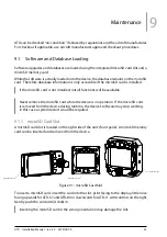
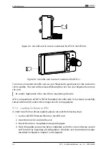
Страница 40: ...o all FAT or FAT32 formatted microSD cards It has been successfully tested with microSD cards with a storage size of 2 to 64 gigabytes 9 1 2 Loading Software to ATD In order to perform a software upda...

Страница 41: ...oSD card at a time Multiple files on the microSD card will cause the device to not update properly 9 1 4 Special Update Instructions from Version 1 5 or 1 7 to 1 8 or later The update to version 1 8 r...

Страница 42: ...ial anti reflective coating that is very sensitive to waxes and abrasive cleaners It is very important to clean the display using a clean lint free cloth and an eyeglass lens cleaner that is specified...

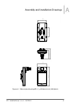
Страница 43: ...Assembly and Installation Drawings A 100 49 50 49 45 15 54 44 50 47 47 Figure A 1 Dimensional drawing ATD 11 all dimensions in millimeters ATD Installation Manual rev 3 0 2019 05 09 37...

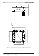
Страница 44: ...Assembly and Installation Drawings air avionics 54 8 61 5 26 3 3 5 4x M3 r 28 5 r 3 3 5 Figure A 2 Dimensional drawing ATD 57 all dimensions in millimeters 38 ATD Installation Manual rev 3 0 2019 05 0...

Страница 45: ...air avionics A Assembly and Installation Drawings 83 83 62 93 62 93 79 47 53 01 24 25 Figure A 3 Dimensional drawing ATD 80 all dimensions in millimeters ATD Installation Manual rev 3 0 2019 05 09 39...

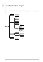
Страница 46: ...UPPLY VOLT Sup ply Voltage Level INFO MAINTENANCE UPDATE BOOT LOADER Install new bootloader from microSD card P N Hardware Partnumber BLVER Bootloader version BUILD Build iden tification DATABASES FLA...

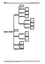
Страница 47: ...LUMINATION LIGHTING BUS LIGHTING BUS MAX LIGHTING BUS voltage for maxi mum illumination intensity Values from 0V to 100V Default 12 00V LIGHTING BUS MIN LIGHTING BUS voltage for mini mum illumination...

Страница 48: ...OFF Default OFF UNITS VERT RATE KN Knots FPM Feet per Minute MPS Meters per Second default ALTITUDE FT Feet M Meters de fault DISTANCE ft Feet M Meters SM Statute Miles NM Nautical Miles KM Kilometers...

Страница 49: ...B 15HD to RJ 45 cable including pin numbers Pin Name Pin number RJ 45 Pin number D SUB 15HD Aircraft Ground GND 1 14 Aircraft Ground GND 2 5 RS 232 ATD Transmit Data TXD 3 3 RS 232 ATD Receive Data RX...

Страница 50: ...FLARM compatible TRAFFIC DISPLAY The default configuration on this port GARMIN TIS will not work 1 1 TRX 1500 or TRX 1500A System B394 AIR TRAFFIC DISPLAY D SUB 15HD to RJ 45 cable included with deli...

Страница 51: ...please make sure to configure TRX 2000 PORT 3 to FLARM compatible TRAFFIC DISPLAY The default configuration on this port GARMIN TIS will not work 1 1 TRX 2000 System B394 AIR TRAFFIC DISPLAY D SUB 15H...

Страница 52: ...PowerFLARM CORE Use the factory default configuration on PORT 1 PowerFLARM CORE or PowerFLARM CORE PURE B394 AIR TRAFFIC DISPLAY D SUB 15HD to RJ 45 cable included with delivery 1 1 ATD 57 AIR TRAFFI...

Страница 53: ...URE B394 AIR TRAFFIC DISPLAY D SUB 15HD to RJ 45 cable included with delivery 1 If running on batteries PowerFLARM PORTABLE is not capable of powering ATD 57 Make sure PowerFLARM PORTABLE is powered e...

Страница 54: ...6 Y Adapter Use the factory default configuration on this port B394 AIR TRAFFIC DISPLAY D SUB 15HD to RJ 45 cable included with delivery 1 1 B256 RJ 45 Y Adapter FLARM power supply ATD 57 AIR TRAFFIC...

Страница 55: ...nd six of the cable Any LX FLARM device with RJ12 Jack and FLARM compatible pinout B394 AIR TRAFFIC DISPLAY D SUB 15HD to RJ 45 cable included with delivery 1 1 B395 RJ45 Jack to RJ12 Plug adapter cab...

Страница 56: ...AIR TRAFFIC DISPLAY D SUB 15HD to RJ 45 cable included with delivery B149 RJ12 Connection Kit for AIR Connect AIR TRAFFIC DISPLAY ATD 57 AIR TRAFFIC DISPLAY main unit Figure C 8 LX FLARM installation...

Страница 57: ...EM RS 232 send data TX TRAFFIC SYSTEM RS 232 receive data RX TRAFFIC SYSTEM Ground GND TRAFFIC SYSTEM WITH FLARM TRX NMEA INTERFACE NOT CONNECTED NOT CONNECTED x x x x x NOT CONNECTED x x x x x NOT CO...

Страница 58: ...been checked 4 Interference checks have been performed 5 Version check has been performed E 3 Device Configuration 1 The device has been configured according to requirements for this specific install...

Страница 59: ...l INTENSITY Minimum INTENSITY Maximum INTENSITY If LIGHTING BUS selected LIGHTING BUS source If LIGHTING BUS selected LIGHTING BUS minimum If LIGHTING BUS selected LIGHTING BUS maximum F 1 4 Power On...

Страница 60: ...rate units Meters per second Feet per minute Knots F 2 2 Other view options DARK STYLE ON OFF OWN SHIP SYMBOL MOTORPLANE GLIDER TARGET SELECT ON OFF HEAD ON ALARM ON OFF F 3 Traffic System Please note...

Отзывы: