3. Interfaces
air
avionics
1.22
2.14
ENABLE (EN)
SWITCH
1.22
2.14
ENABLE (EN)
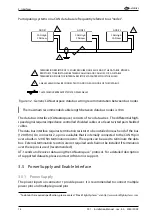
Figure 3.3.: If the AT-1 is not installed in combination with an AIR Traffic Display, or another
device compatible to the enable-interface, either Pin 1.22 or pin 2.4 have to be
connected to GND. Connection can be made permanently (the AT-1 is always
switched on if supply power is present) or over a switch (AT-1 is only switched
on if the connection to GND is made)
3.6 Audio Output
The AT-1 audio output on pin 1.15 provides an audio signal to an audio panel, an intercom,
or an external speaker.
The audio signal can either be configured as a voice output (traffic warnings, status
messages) or a beep tone (sine wave).
The audio output volume level is adjustable by means of a configuration parameter
(permanently configured to a certain level) or an analog voltage present at pin 1.6 (can be
changed in-flight), e.g. by using a rotary potentiometer that is installed into the instrument
panel.
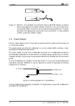
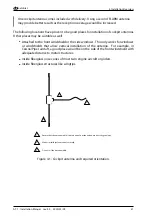
In some installations, for example if connecting the AT-1 to an avionics audio panel (input
impedance typically 500Ohm), it may be required to install an impedance matching
transformer 1:4 or similar.
AT-1 AUDIO OUT
AUDIOPANEL INPUT
1:4
AUDIOPANEL - / GND
Figure 3.4.: Wiring diagram of a 1:4 transformer.
Various configuration parameters are available. For details, please consult the configuration
parameter list in appendix F.
16
AT-1
·
Installation Manual
·
rev. 4.0
·
2020/01/09

