background image

3. Getting started


ANET1553-x 

User’s Manual 

24 


3.7  Booting the device into emergency mode 

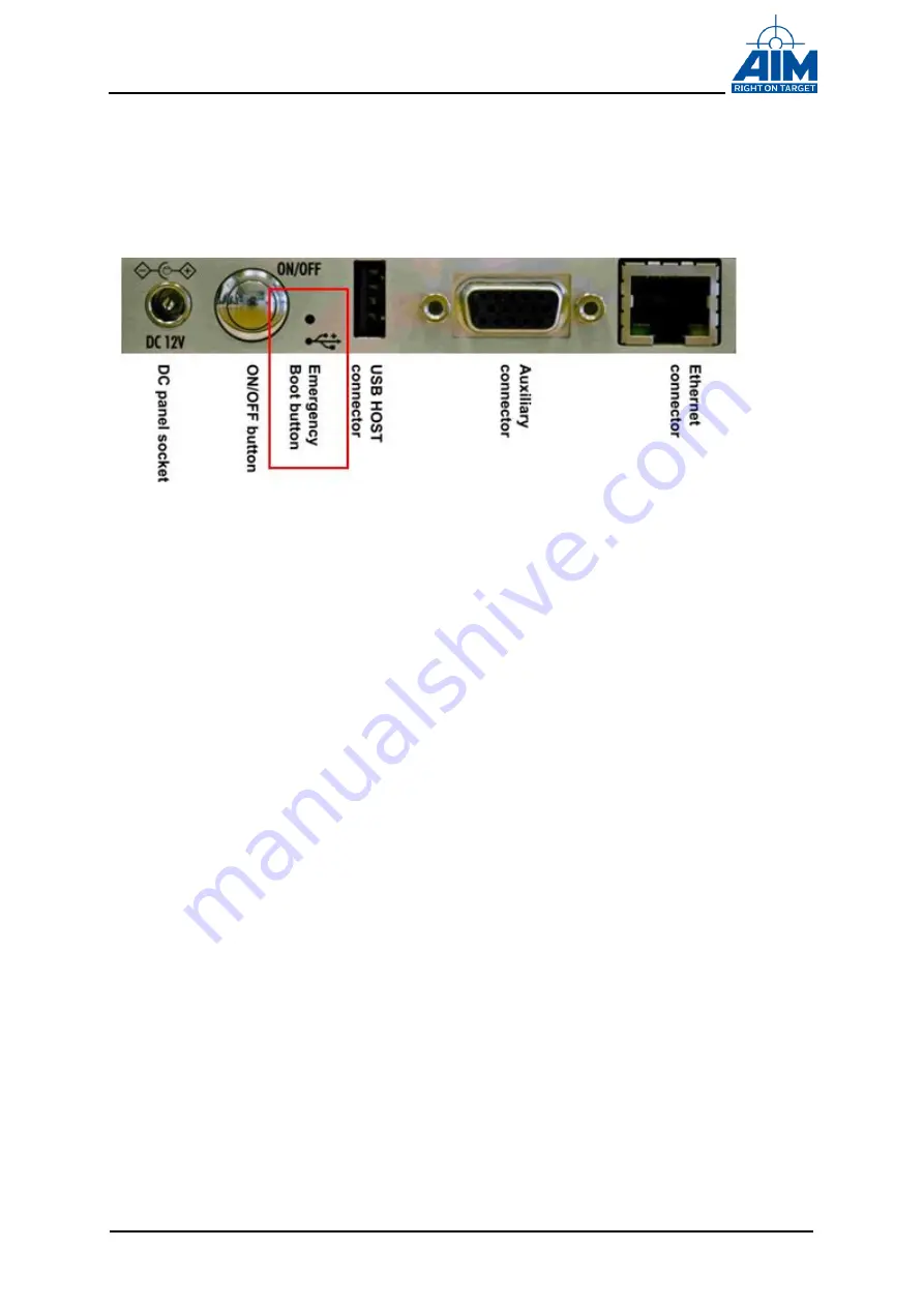
The  ANET1553  device  offers  an  ‘Emergency  Boot  Button’  on  the  back  panel  of  the 
device: 


Figure 3.7-1  Emergency Boot Button 


The emergency system can be used to start up the device whenever the normal system 
start up does not work. It can be used to reset the device to factory settings or perform 
software updates. 
 
Press  the  emergency  button  while  powering  on  the  device,  e.g.  with  a  paper-clip,  in 
order  to  boot  the  ANET1553  into  the  emergency  mode.  The  emergency  mode  boot  is 
indicated by a red blinking LED. When booting into the emergency mode, the device will 
start up with its default factory settings, e.g. user name, password and IP address. You 
are able to connect to the ANET1553 device with your web browser now. 
 

3.8  How to connect Applications to the ANET1553 

The  following  chapters  describe  how  to  connect  an  ANET1553  with  PBA.pro  or  any 
customer specific application using the AIM Application Programming Interface Library 
(API-Library). 
 

3.8.1  Connect to a ANET1553 with PBA.pro 

Open the “Help\About\Settings” tab in PBA.pro and setup the “servers_ppmil” setting to 
the  alias  name  or  IP  address  used  for  your  ANET15

53,  e.g.  “ANET1553-3.local”  (see 

Figure 3.8-1 below) and re-start the PBA.pro. 
 

Содержание ANET1553 Series

Страница 1: ...V01 33 Rev A March 2018 ANET1553 x Single or Dual Stream MIL STD 1553A B Test Simulation Module for Standard Ethernet Users Manual ...

Страница 2: ......

Страница 3: ...ANET1553 x User s Manual i ANET1553 X User s Manual for Single Dual Stream MIL STD 1553 Ethernet Interface V01 33 Rev A March 2018 AIM No 60 11E2x 16 0133 A Users Manual ...

Страница 4: ...nline com AIM GmbH Munich Sales Office Terofalstr 23a D 80689 München Germany Phone 49 0 89 70 92 92 92 Fax 49 0 89 70 92 92 94 salesgermany aim online com AIM USA LLC Seven Neshaminy Interplex Suite 211 Trevose PA 19053 Phone 267 982 2600 Fax 215 645 1580 salesusa aim online com AIM GmbH 2018 Notice The information that is provided in this document is believed to be accurate No responsibility is ...

Страница 5: ...F Scherer Due to a mismatch in the discrete description the user manual must be corrected Fault Correction Technical Data Modification related to the changed power on behaviour Certificate of Volatility Power behaviour instant power How to connect the ANET Table Adapter V01 20 Rev A 06 12 2016 M Haag Modified BSP sections to match the standard BSP V01 30 Rev A 29 03 2017 M Schuessele ANET Rugged A...

Страница 6: ...ANET1553 x User s Manual iv THIS PAGE IS INTENTIONALLY LEFT BLANK ...

Страница 7: ...11 3 1 3 The AIM Network Detection Tool 12 3 1 3 1 Installing Apple Bonjour 12 3 1 3 2 Using the AIM Network Detection Tool 13 3 1 4 Configuring the ANET1553 14 3 1 5 Configuring basic properties 15 3 1 5 1 Setting the IP Address 15 3 1 5 2 Configuring Wireless Network Interfaces 16 3 1 5 3 Configure System Services 19 3 1 5 4 Discrete I O state 19 3 1 5 5 Check System Log File 20 3 1 5 6 Re Boot ...

Страница 8: ...s 43 6 2 Single Function Version 43 7 Frequently asked questions 45 8 Technical Data 47 9 Notes 51 9 1 Acronyms 51 10 Apendix 53 10 1 ANET Table Adapter Panel for ANET D Variants 53 10 2 How to connect the ANET Table Adapter 53 10 3 ANET Rugged Housing Variant 56 10 3 1 Hardware Installation 56 10 3 2 Connectors 56 10 3 3 DC Power IN Reset and Power Up Control Connector 57 10 3 4 MIL STD 1553 Inte...

Страница 9: ...e 2 2 13 ANET Web Configuration Tool Update finished 23 Figure 2 2 14 ANET Web Configuration Tool Update Log File 23 Figure 2 2 15 Emergency Boot Button 24 Figure 2 2 16 Connect to ANET1553 with PBA pro 25 Figure 2 2 17 Connect to ANET1553 with PBA pro 25 Figure 2 2 18 Pigtail Connector 27 Figure 2 2 19 Direct Coupling 27 Figure 2 2 20 Stub Coupler 28 Figure 2 2 21 Transformer Coupling 28 Figure 2...

Страница 10: ...Manual viii LIST OF TABLES Figure Title Page Table 2 2 1 1 Pinout Auxiliary Connector 8 Table 4 7 1 1 Time Tag Format 37 Table 10 3 3 1 Pinout Power Connector 57 Table 10 3 4 1 Pinout MIL STD 1553 Interface Connector 58 ...

Страница 11: ...d as a standalone module connected with an Ethernet link to a host computer An external power supply wall adapter is used to power the ANET module Different coupling modes such as Transformer Coupling Network Emulation and Direct Coupling are available for each MILBus channel and can be programmed using the on board relays The MILBus Signals are connected to Twinax connectors The hardware architec...

Страница 12: ...t between the documents referenced and the contents of this document the contents of this document shall have precedence 1 2 1 Industry Documents 1 MIL STD 1553B Department of Defence Interface Standard for Digital Time Division Command Response Multiplex Data Bus Notice 1 4 January 1996 1 2 2 Product Specific Documents 2 AIM MIL STD 1553 Reference Manual Detailed description of the programming in...

Страница 13: ...rk Detection Tool These files are automatically copied to the system e g HOST PC by installing the BSP software package The software is available on DVD from AIM or via a download from AIM Online instructions how to obtain the BSP via a download from AIM Online are described in the following chapter To install the BSP software from the AIM provided DVD or a download from AIM Online www aim online ...

Страница 14: ...oose the directory where the BSP is to be installed Default locations can also be used The BSP installation will result in the creation of the following Program Folder icon Start All Programs AIM GmbH MIL STD 1553 Windows BSP 12 x y The AIM GmbH sub directory will be located by default in the directory C Program Files The Program Files directory is located on the drive which was chosen during BSP ...

Страница 15: ...2 lib64 Application Programming Interface DLL Files and Libraries required to develop an application for Windows systems Include Application Programming Interface headers required to develop an application for Windows systems Board Update A compressed on board software firmware update file Doc A set of reference and user manuals Sample Sample project and source files for Microsoft Visual Studio 20...

Страница 16: ...llowing connectors Front panel Up to four TWINAX connectors at the front side providing the MIL STD 1553 channels Back panel Auxiliary 15 pin High Density DSUB connector for the Trigger IN OUT signals IRIG IN OUT for multi channel time tag synchronization and the eight Discrete IN OUT signals A RJ45 Ethernet plug for connecting the ANET1553 with a Network Host USB Type A host connector e g for con...

Страница 17: ...rface Connectors For connecting to the external MILBus up to four TWINAX connectors respectively two TWINAX connectors for a single channel ANET1553 1 Module are provided at the front panel The figure at the right side shows the pin out from the TWINAX connector Figure 2 2 3 TWINAX connector ...

Страница 18: ...te I O 4 2 IRIG Out 7 Discrete I O 2 12 Discrete I O 5 3 Trigger OUT CH1 8 Trigger OUT CH2 13 Discrete I O 6 4 Trigger IN CH1 9 Trigger IN CH2 14 Discrete I O 7 5 GND 10 Discrete I O 3 15 Discrete I O 8 Table 2 2 1 1 Pinout Auxiliary Connector 2 2 1 3 USB TYP A Host connector A TYP A host USB connector is provided e g for connecting external storage devices or an optional WLAN stick 2 2 1 4 DC Pow...

Страница 19: ...llowing Power ON OFF Normal operation 1 LED RED illuminated Illuminated during power on cycle 2 LED BLUE fast pulsing Fast pulsing blue during ASP LINUX boot up 3 LED BLUE slow pulsing Slow pulsing blue when the on board OS has been boot up ready for operation 4 LED RED fast pulsing Fast pulsing red during ASP LINUX shutdown power off cycle and during re boot commanded via the ANET Web Configurati...

Страница 20: ...dule will start up w o requiring an explicit power button press as long as the external power supply is present the module can powered down shutdown and powered up via pressing the power button Interrupting the external power or pressing the power button longer than 3 seconds will force a power off without shutdown power down of the OS Note It is recommended but not mandatory to shutdown power dow...

Страница 21: ...y standard twisted pair cable with RJ45 plugs can be used The DHCP server will automatically assign an IP Address for each ANET1553 in a network 3 2 2 The Network doesn t provide a DHCP sever Either the ANET1553 has a direct connection between an Ethernet port of a PC or is connected to a Ethernet Network via a Switch Both the ANET1553 module and the configuration system e g PC should be powered o...

Страница 22: ...g wg zeroconf charter in order to find any ANET1553 modules in your network The AIM Network Detection Tool makes use of Apple Bonjour a freeware Zeroconf implementation How to install and use Apple Bonjour and how to use the AIM Network Detection Tool is described in the following sections 3 3 1 Installing Apple Bonjour For Windows OS download the Apple Bonjour installation executable from www app...

Страница 23: ...e ANET1553 Software DVD to start the AIM Network Detection Tool After some seconds it will show all ANET1553 modules visible in your network A double click on any ANET1553 module in the list will open the default web browser of the system and forward you to the web configuration page of the corresponding ANET1553 module The module s IP address can also be resolved by the board s alias which is sho...

Страница 24: ... browser address bar to connect to and to configure the ANET1553 First of all you have to enter a user name and password on the login screen the default login is User Name user Password aim After a successful login you will be forwarded to the System Overview page This page shows a summary of the current system status as shown in the figure below Figure 3 4 1 ANET Web Configuration Tool System Ove...

Страница 25: ...ur applications to the new alias name The default alias is ANET1553 x x Serial Number 3 Getting started ANET1553 x User s Manual 15 Note It is recommended to change the password default aim when using the ANET1553 module the first time 3 5 1 Setting the IP Address Click on the Network Settings tab in the navigation bar You will now see a page where you can set either a static or dynamic DHCP IP ad...

Страница 26: ... settings which have to be configured Mode Set to Managed if you want to connect to a network with a central wireless access point Use Ad Hoc also called IBSS if you want to join a peer to peer network without central access point ESSID This is the alphanumeric ID of the wireless network the ANET1553 device shall connect to In Managed mode the AP defines this ID In Ad Hoc mode all participants of ...

Страница 27: ...s access point The ANET1553 device can join this network So it is possible to control the ANET1553 device with the Windows based host device over the wireless connection The setup of the wireless access point needs to be done via the Windows netsh command interpreter since the setup is no longer possible via the Windows 8 x GUI due to network safety reasons Following steps outline the necessary ne...

Страница 28: ...e allow ssid NETWORK_NAME key YOUR_PASSW The hosted network will use WPA2 encryption per default See the displayed settings after the call of a show hostednetwork command see below at para 6 5 start the hosted network via the following input at the netsh wlan prompt start hostednetwork or netsh wlan start hostednetwork from standard cmd prompt 6 The hosted network can be checked via the following ...

Страница 29: ... or service for applications which use the AIM 1553 ApiConnectToServer call in order to establish a connection to an ANET1553 That API function can either use the alias name or the IP address of an ANET1553 Note If the ANS1553 has been switched off the 1553 API is no more able to connect to the ANET1553 Figure 3 5 4 ANET Web Configuration Tool Services 3 5 4 Discrete I O state Click on the Discret...

Страница 30: ... module over Ethernet using the Reboot or Shutdown function in this Tab 3 5 7 Reset Settings to Factory default Click on the Maintenance tab in the navigation bar see the figure below Reset To Factory Defaults allows to reset all settings to the factory defaults To do this first go to the Update Tab and re boot the ANET1553 to Maintenance mode by a mouse click to the Reset to maintenance system bu...

Страница 31: ...3 to switch to maintenance mode Wait until the re boot has been finished then log in re connect to the ANET1553 again Click again on the Update tab in the navigation bar and choose the update file filename tar gz e g anet1553 update tar gz and start the update The default location of the update file in the BSP is Onboard SW update components Figure 3 6 1 ANET Web Configuration Tool Update tab ...

Страница 32: ...ning Figure 3 6 2 ANET Web Configuration Tool Update is running If the update has been finished successfully the status should look like shown below Press Finish Update button to finish the update and to download the Log File In case any errors have been occurred during the update may be to protocol can be usefull for the factory for further investigations ...

Страница 33: ...3 Getting started ANET1553 x User s Manual 23 Figure 3 6 3 ANET Web Configuration Tool Update finished Figure 3 6 4 ANET Web Configuration Tool Update Log File ...

Страница 34: ...e emergency mode boot is indicated by a red blinking LED When booting into the emergency mode the device will start up with its default factory settings e g user name password and IP address You are able to connect to the ANET1553 device with your web browser now 3 8 How to connect Applications to the ANET1553 The following chapters describe how to connect an ANET1553 with PBA pro or any customer ...

Страница 35: ...Connect to ANET1553 with PBA pro After a re start PBA pro should show the available ANET1553 MIL Resources The figure below shows how it looks like for an ANET1553 2 For an ANET1553 1 only the MIL Resource is shown Figure 3 8 2 Connect to ANET1553 with PBA pro ...

Страница 36: ...board by calling operating system routines to open the AIM board and initialize a shared memory area for host to target communication For further informations see the AIM Software Reference Manual 3 9 Connecting the ANET1553 to the MIL STD 1553 Bus The MIL STD 1553 Specification clearly defines the process of coupling subsystems to the MIL STD 1553 Bus This connection called a stub has the followi...

Страница 37: ...ns under one foot in length Since a Direct Coupled stub provides only limited isolation in the event of a device subsystem or terminal short Transformer Coupling is normally the recommended method of connecting to the bus Figure 3 9 1 Pigtail Connector AIM provided Pigtail Connector A B T T T T Terminators A B Bus A Bus B Stub Length One Foot Max Figure 3 9 2 Direct Coupling ...

Страница 38: ... Direct Coupling The electrical isolation prevents a terminal fault or stub impedance mismatch from affecting bus performance Figure 3 9 3 Stub Coupler Connecting to the bus using Transformer Coupling requires a Coupler for each subsystem terminal device and proper termination on the bus Figure 3 9 4 Transformer Coupling Aircraft or Lab Cable Bus Coupler 78Ω Termination Bus Coupler Bus B A B AIM M...

Страница 39: ...ed for any bus coupling The Network Coupling mode selected by the user via software controls provides a terminated MILbus network simulation on the ANET1553 to allow a direct connection between the ANET1553 and the external terminal 3 9 4 Isolated Coupling In Isolated Coupling mode the ANET1553 MIL STD 153 frontend is physically suspended from the ANET1553 TWINAX frontend connectors via relays ANE...

Страница 40: ...3 Getting started ANET1553 x User s Manual 30 THIS PAGE INTENTIONALLY LEFT BLANK ...

Страница 41: ...1 only provides one MIL STD 1553 channel The ANET1553 comprises the following main sections System FPGA Global RAM BIU Section Physical I O Interface with up to two Dual redundant MIL STD 1553B channels with programmable output Amplitude and Coupling Network IRIG B 122 Time Code Processor with Free Wheeling Function ASP Section with local ASP RAM Figure 3 9 1 Block Diagram ANET1553 2 ...

Страница 42: ...he BIU processor the MIL STD 1553 Encoder Decoder logic to handle up to two MIL STD 1553 channels the Trigger Logic to handle the Trigger I O signals in BC RT and BM operating modes and a SPI Flash for BIU Processor Boot all implemented in the FPGA 4 3 1 MIL STD 1553 Encoder The MIL STD 1553 encoder comprises a Manchester Encoder with full error injection capability as required by the Remote Termi...

Страница 43: ... to the BC BM and RT FPGA internal trigger logic simultaneously and is caught by the operating mode BC RT BM where the trigger mode is activated The external Trigger IN pulse length must be at least 75 nanoseconds 4 4 Physical MIL STD 1553B I O Interface MILBus Coupling Modes Up to two dual redundant MIL STD 1553A B channels are available The on board MILBus Transceivers provide variable output am...

Страница 44: ...tation of the host connection via a Standard Ethernet RJ 45 connector Furthermore the also SOC built in USB interface has been made available to the user for mounting external mass data storage devices or e g a WLAN stick for wireless 4 6 Discrete I Os The ANET1553 module provides eight user programmable Discrete I O signals Discrete input signals are always active whereas the discrete output sign...

Страница 45: ...istor must limit the current through the open collector transistor to max current see technical data chapter for details Otherwise the open collector transistor can be damaged EMC aspects are covered by filter circuitry GND Discrete IO Pin Front Connector ANET1553 Board Pulldown Resistor Current limiting Resistor 1 KΩ 5V Current limiting Resistor 10 KΩ Discrete output circuitry Discrete input circ...

Страница 46: ...NET1553 ANET1553 x User s Manual 36 Discrete IO Pin Front Connector Off Board User Voltage Customized Discrete Output Rserial ANET1553 Board GND FPGA Output Pin Figure 4 6 2 Discrete I O Pin off board user series resistor ...

Страница 47: ...nel synchronization On the ANET1553 a freewheeling IRIG function is implemented If no external IRIG signal is detected the Time Code Processor TCP switches automatically to the freewheeling operation mode If an external IRIG B signal is detected in freewheeling mode the Time Tag is automatically synchronized to this external IRIG B signal The time tag on the board is generated in the format shown ...

Страница 48: ...on required b Multiple AIM Modules with no common synchronization requirement No connection required c Single or multiple AIM Module s with external IRIG B source Connect external IRIG B source to IRIG IN and GND of all modules d Multiple AIM Modules with no external IRIG B source internally synchronized Connect the IRIG OUT signal and the GND of the module you have chosen as the time master to al...

Страница 49: ..._sample_project exe from within the sample directory Start All Programs AIM GmbH PCI 1553 Windows BSP Vxxxx 1553_sample_project The 1553_sample_project program opens a board and provides a selection of sample functions to execute For further information regarding development of a 1553 application software program to interface to the ANET1553 module see the MIL STD 1553 Reference Manual Note The pr...

Страница 50: ...TD 1553 Windows BSP 12 x y Sample and open the solution 1553_sample_project sln Figure 4 7 1 File Structure Sample project To add the proper search paths for the include files 1 Right click the project and select Properties 2 Select the C General 3 Additional Include Directories must contain the include directory c Program Files AIM GmbH MIL STD 1553 Windows BSP 12 x y include Then select the OK b...

Страница 51: ...enter _AIM_WINDOWS then select OK Figure 4 7 3 Sample project preprocessor definitions To add the proper library 1 Right click the project and select Properties 2 Select the Linker Input 3 Under Additional dependencies if not already included enter api_mil 24 lib To add the proper library path 1 Right click the project and select Properties 2 Select the Linker General 3 Under Additional library di...

Страница 52: ... 42 Figure 4 7 4 Sample project library path To Build and Execute a Sample Program 1 Build Rebuild Solution 2 The executable will be stored in the Debug or Release subdirectory 3 The api_mil 24 dll will be loaded from the Windows system directory 4 Run the executable ...

Страница 53: ...vides a BC and Multi RT Simulator with Mailbox Monitor functionality but doesn t include the Chronological Monitor function 6 2 Single Function Version The Single Function functionality is intended for applications where all functions should be available but they don t need to be available concurrently In general all functions are available but they are not available simultaneously that means only...

Страница 54: ...6 Single or Simulator Only Functions ANET1553 x User s Manual 44 THIS PAGE INTENTIONALLY LEFT BLANK ...

Страница 55: ...our Web Browser The emergency system accepts the default user user and password aim Go to the Maintenance tab and press the Reset To Factory Defaults button This will reset the user name and password of the device The ANET1553 device does not finish the boot up process endlessly Do power on the ANET1553 while pressing the Emergency Boot Button on the back panel of your device This will start the e...

Страница 56: ...7 Frequently asked questions ANET1553 x User s Manual 46 THIS PAGE INTENTIONALLY LEFT BLANK ...

Страница 57: ...tuck at low or high error in selected word and bit position Gap error between selected words for 0 5 to 7 5 µs in 0 5µs steps Bit count error on selected word 3 bits Parity error on selected word Decoder For each BIU one Manchester Decoder with Parity checker and error detection Single implementation with bus switching logic not redundant Full error detection and indication inter word gap timer wi...

Страница 58: ...inter message gap measurement 100µs an internal timer is used with 250 ns resolution MIL STD 1553 Bus Front End The physical I O Interface with one or two dual redundant MIL STD 1553 streams It consists of the MIL STD 1553B transceiver and a respective transformer The output voltage of the transceiver is adjustable Bus coupling modes Transformer coupled Direct coupled Network coupled Transformer c...

Страница 59: ...ote When the default 5V for the discrete outputs are not used provide a serial resistor in line with the open collector transistor If using a discrete pin as input make sure that the output mode is set to default before connecting an external voltage Otherwise the transistor can be damaged Voltage Supply Input Voltage Range VIN 9VDC 15VDC 12VDC recommended Power Consumption Stand by PIN 100mW Oper...

Страница 60: ...8 Technical Data ANET1553 x User s Manual 50 THIS PAGE INTENTIONALLY LEFT BLANK ...

Страница 61: ...P Gigabit Transceiver GND Ground IRIG B Inter Range Instrumentations Group Time code Format Type B I O Input Output JTAG Joint Test Action Group IEEE 1149 1 Boundary Scan LCA Logic Cell Array XILINX Programmable Gate Array LED Light emitting Diode MIL STD Military Standard MILbus MIL STD 1553 bus NTRAM No Turnaround Random Access Memory PBI Physical Bus Interface PROM Programmable Read Only Memory...

Страница 62: ...9 Notes ANET1553 x User s Manual 52 THIS PAGE INTENTIONALLY LEFT BLANK ...

Страница 63: ...k screw and Emergency Boot button ON OFF button USB HOST connector Ethernet connector 10 2 How to connect the ANET Table Adapter Figure 10 2 1 ANET Docking Connector Step1 Plug in the ANET Table Adapter to the ANET Module docking connector at the Backpanel Step 2 For locking the Table Adapter with the ANET Module use the screw beside the Power ON OFF Button Figure 10 2 2 ANET Table Adapter ...

Страница 64: ...10 Apendix ANET1553 x User s Manual 54 THIS PAGE INTENTIONALLY LEFT BLANK ...

Страница 65: ...10 Apendix ANET1553 x User s Manual 55 ANET 1553 X Rugged 1553 Test Simulation Module for Standard Ethernet rugged variant Add on ...

Страница 66: ...re 2 MIL STD 1553 Frontend Connector one 9 pin DSUB connector 3 AUX Connector Trigger Discrete IRIG I O Auxiliary 15 pin High Density DSUB connector for the Trigger Input Output signals IRIG B Input Output for multi channel time Synchronisation and eight Discrete Input Output signals 4 USB Type A host connector e g for connecting an external storage device or an optional WLAN stick 5 Ethernet RJ45...

Страница 67: ...ly and controlling of Emergency Reset and manual Power Up Down Pin No Signal 1 GND 2 Emergency Reset 1 3 Emergency Reset 2 4 Power Button 1 5 VCC 6 Power Button 2 SHIELD Table 10 3 3 1 Pinout Power Connector Note The pins 2 3 are intended for the Emergency Reset Emergency Mode push button and pins 4 6 are intended for a power push button 1 5 4 3 2 ...

Страница 68: ...inout is shown below Pin No Signal 1 MILBUS channel 1 A TRUE 2 MILBUS channel 1 A COMPLEMENT 3 4 MILBUS channel 1 B TRUE 5 MILBUS channel 1 B COMPLEMENT 6 MILBUS channel 2 A TRUE 7 MILBUS channel 2 A COMPLEMENT 8 MILBUS channel 2 B TRUE 9 MILBUS channel 2 B COMPLEMENT Table 10 3 4 1 Pinout MIL STD 1553 Interface Connector Figure 10 3 1 MIL STD 1553 Connector front view ...

Страница 69: ... cycle 6 Light BLUE fast pulsing Fast pulsing blue during ASP LINUX boot up 7 Light BLUE slow pulsing Slow pulsing blue when the on board OS has been boot up ready for operation 8 Light RED fast pulsing Fast pulsing red during ASP LINUX shutdown power off cycle and during re boot commanded via the ANET Web Configuration tool Maintenance Mode e g running an update 1 Light RED fast pulsing Fast puls...

Страница 70: ...l power or making a shortcut between Pin4 and Pin6 longer than 3 seconds will force a power off without shutdown of the OS see also chapter Connectors Note It is recommended but not mandatory to shutdown power down the module via the ANET web frontend maintenance page or SSH shell command power off as user root to avoid any user data corruption especially when having customer applications scripts ...

Страница 71: ...GMA 0B 045 DN connector and cable protection 15 pol high density DSUB female Trigger IN and OUT Discrete I O IRIG IN and IRIG OUT 9 pol DSUB female MILbus Channel 1 2 signals USB Type A connector RJ45 Ethernet Connector female Voltage Supply Input Voltage Range see product label on module VIN 9 36VDC or 18 50 VDC Power Consumption Stand by PIN 100mW Operational IDLE PIN 2 8W Operational 1 channel ...

Страница 72: ...sor Boot Process to Sanitize Erase Type Serial SPI Flash Size 8 Mbit User Modifiable Yes No Function LS BIU2 Processor Boot Process to Sanitize Erase Type Serial SPI Flash Size 64 Mbit User Modifiable Yes No Function FPGA Boot Process to Sanitize Erase Type NAND Flash Size 1 GByte User Modifiable Yes No Function LINUX Program Data Firmware Process to Sanitize Erase Media Does the item contain medi...

Отзывы: